ThreadTracer Online Documentation ThreadTracer for GibbsCAM
header_logo
© 2014-2024 Cato Hagen
ThreadTracer

Home Features Documentation Media Updates Download Purchase Resellers
Additional Plugins

MillTracer MillBlunt WaveThread Other Plugins

Customer Login

Login or Register
Contact

Contact Info
ThreadTracer 4 - Online Guide   Switching Spindle Auto ClearanceAdvanced Entry & Retract      

   Use mouse and click in the interface to jump down to the relevant section for any spesific element ( tabs,buttons or options )
BUTTRESS BUTTRESS BUTTRESS BUTTRESS BUTTRESS BUTTRESS BUTTRESS tooling tool_presetter tool_geometry face_relief b-axis diamond style delay est_runtime rough_cut fin_cut material do_rough do_rough process online_guide save_data do_it

Buttress Thread \\ Tooling (Tab 3):

Tooling (Back to top)

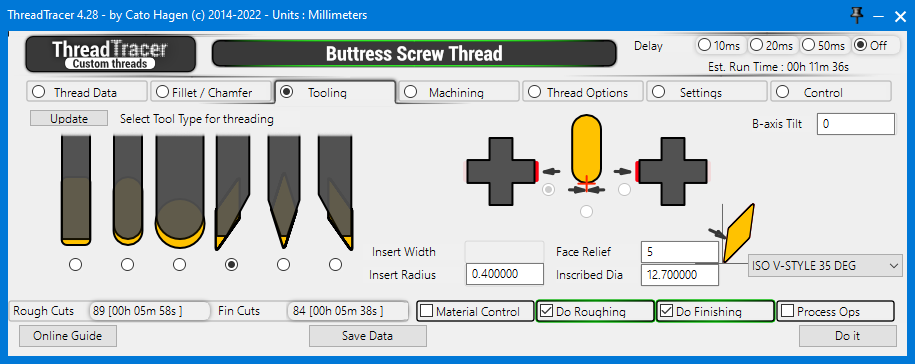
Select what type of tool to use for machining the thread.


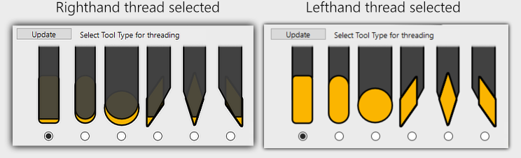
Tools shown in the window will be correctly represented for Righthand and Lefthand threads, click the Update button if they are not shown correctly.

Supported tools

  • Grooving tool, rectangular with radius on corners.
  • Grooving tool, with full radius.
  • Round Insert (Button Insert).
  • Diamond Insert - Pointing towards the main spindle.
  • Diamond Insert - Pointing straight down.
  • Diamond Insert - Pointing away from the main spindle. (Points towards the sub-spindle)

  • Tool Presetter (Back to top)

    Use the 3 radio buttons to select where on the insert/tool presetter you measured the Z offset for the tool. (right/left side or center)

    Tool presetter Z axis touch off point : Left Side
    Tool Z axis Zeropoint : Center
    Tool presetter Z axis touch off point : Right Side

    Tool Geometry (Back to top)

  • Insert Width : Enter the insert width for grooving tools. For diamond tools this input box is disabled.
  • Insert Radius : Enter the insert corner tip radius. On diamond tools this is the tip radius.

  • Tool Geometry & Tool Parameters

    Face Relief (Back to top)

    Enter the insert face relief and Inscribed Diameter for diamond tools. A standard holder will usually hold the insert with a 5 degree face relief.

    Face Relief

    Diamond Style (Back to top)

    From the dropdown, select diamond style for insert. ISO V-STYLE 35°, D-STYLE 55° and C-STYLE 80° are supported.
    Its important to select the correct style, Face Relief and Inscribed Diameter as the geometry of the tool are used to detect tool gouging against the thread profile.

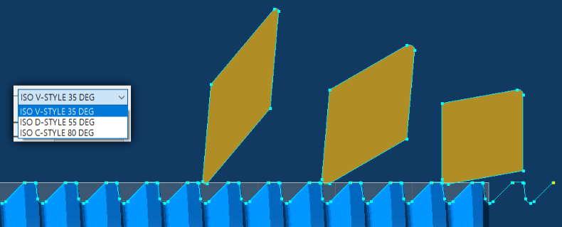
    ISO V-STYLE 35°, D-STYLE 55° and C-STYLE 80° Diamond Style Inserts

    Generated tools in GibbsCAM (link) (Back to top)

    ThreadTracer will always build a new formtool with the shape defined by insert width and insert radius.
    If a diamond tool is selected, it will build this tool with style selected, insert radius and face relief.


    If you need to define your own tool, its important to set the same tool parameters as insert width and insert radius.
    You can define your own tool by editing the existing tool built by ThreadTracer, as long as the Comment is not changed. ThreadTracer will continue to use this tool when creating new threading operations.

    You can also copy the tool comment line from a generated tool into an existing tool. Then delete the generated tool and create GibbsCAM operations for the thread and it will use the same tool.
    This way you can define your tool to be used in multiaxis machines with multiple tool groups and sub spindle.

    Tool Comments built by ThreadTracer always look similar like this : ThreadTracer EXT TG=0 HAND=R GROOVE CW=3 R=1.5 PRESET=1
    
    ThreadTracer  = plugin name
    EXT           = external thread
    TG=0          = toolgroup
    HAND=R        = right hand
    GROOVE        = tool type
    CW=3          = insert cutting width
    R=1.5         = insert radius
    PRESET=1      = tool presetter position


    B-axis machines and toolholder orientation (Back to top)

  • B-Axis Tilt : Set the B-axis tilt in degrees. For B-axis machines, the angle set here will be used when creating the tool for machining.
  •     You may experiment here what values to set with a B-axis machine, if the tool requires the B axis to be rotated 45° for the tool to be correct,  the value in ThreadTracer may be 45° (or -45°)


    Control buttons at the bottom (Back to top)

    rough_cut fin_cut material do_rough do_fin process online_guide save_data do_it
    Use the buttons at the bottom of the ThreadTracer dialog to turn on or off actions to make.

    Rough Cuts (Calculated) (Back to top)


    Holds information of the calculated Rough Cuts in the current programmed thread. 'amount of cuts' [ hh:mm:ss ]
    Rough Cuts 60 [ 00h 04m 01s ] means roughing the current programmed thread requires 60 threading passes with an estimated machining time of 4 minutes and 1 seconds.

    Fin Cuts (Calculated) (Back to top)


    Holds information of the calculated Finishing Cuts in the current programmed thread. 'amount of cuts' [ hh:mm:ss ]
    Fin Cuts 112 [ 00h 07m 29s ] means finish machining the current thread requires 112 threading passes with an estimated machining time of 7 minutes and 29 seconds.

    Est. Run Time (Calculated) (Back to top)


    Est. Run Time shows the calculated Run Time for machining, for all Roughing and Finishing passes combined.

    To improve the time estimate, you can set your machine tool Rapid Feedrate in the Settings tab. Your machines rapid feedrate can be found in the parameters of the machine.
    As there are as many rapid moves as feed moves in machining a thread, setting the correct rapid feedrate will allow for a more precise time estimate.

    If you work in metric, set the Rapid Feed in millimeters/minute. If you work in inch, set the Rapid Feed in inches/minute.
    Default values in ThreadTracer are 12000 millimeters/minute for GibbsCAM in metric and 500 inches/minute for GibbsCAM set to inches.


    Material Control ( Checkmark On/Off ) (Back to top)

  • Material Control : This will enable material control, and keep all threading cuts within the set limits. By default the limits are always set to Major and Minor diameter.
  • You can change upper and lower machining limits for Material Control in the Machining Tab.

    Do Roughing ( Checkmark On/Off ) (Back to top)

  • Do Roughing : This will enable roughing of the thread. When enabled it will run the roughing of the selected thread with the set tool parameters when pressing the 'Do It' button.
  • Do Finishing ( Checkmark On/Off ) (Back to top)

  • Do Finishing : This will enable finishing of the thread. When enabled it will run the finishing of the selected thread with the set parameters when pressing the 'Do It' button.
  • Process Ops ( Checkmark On/Off ) (Back to top)

  • Process Ops : This will enable the creation of GibbsCAM threading operations for all the calculated thread coordinates when pressing the 'Do It' button.

  • Do It Button (Back to top)

    Everything in ThreadTracer is controlled by the 'Do It' button.
    You can turn on/off options, generate visual geometry, change cut depths, change tool sizes and everything will be recalculated and updated when you press 'Do It'.
    As long as the 'Process Ops' or 'NC Postprocessor' are disabled, no GibbsCAM operations or g-code will be generated.

    Set up the all the roughing and finishing of the thread and only enable 'Process Ops' when everything seems correct. With 'Process Ops' enabled it will generate GibbsCAM threading operations.
    'Do Roughing' and 'Do Finishing' can be set individually. If only 'Do Finishing' is enabled and 'Process Ops', it will only create GibbsCAM threading operations for the finishing passes.

    Click 'Do It' button to start running the options that's selected.

    As ThreadTracer is an external plugin, there is no 'ReDo' button. If you need to change anything you must delete the threading operations in GibbsCAM and create new ones in ThreadTracer.

    If you delete the threading tool instead, all the operations in GibbsCAM that used that tool will be removed, this is often faster than selecting multiple operations with scrolling for deletion.
    ThreadTracer will always create a new tool based on tools settings from the Tooling tab (Tab 3) if no previous tool exists.

    If you are using NC Tracer to generate g-code for machining, Process Ops should be disabled(off) and instead enable 'NC PostProcessor' in Tab 7.


    Save Data Button (Back to top)

    Click 'Save Data' to store the current thread setup into the GibbsCAM program

    It will create a new data entry if its a new thread, after the thread setup is stored the button will change to 'Update Data'.
    This way you can store and update the same thread entry, and not create a completely new thread entry every time the 'Save Data' is clicked.
    If you need to create a new data entry in the GibbsCAM part, you must close ThreadTracer and restart it, and it will now start with a new data entry.

    With version 4.32 and higher its not necessary to use 'Save' button. All thread data from ThreadTracer are written to each operation and retrievable by using 'Get From Op' button instead.


    These lines of text can also be copied and pasted into other GibbsCAM programs, to quickly recreate the thread without typing in all the parameters again.

    Delay Timer (Back to top)


    Visual Delay Timer for in between each calculated thread pass.
    The Delay Timer can be useful for delaying the visual geometry drawn in GibbsCAM. If something seems off, it can sometimes help track the error with a delay and confirm that every pass is done correctly.
    Delay Timer was initially used in development of ThreadTracer, but kept it as it can be useful to slow things down if there is a suspicion of some passes not being laid out correctly.


    Online Guide Button (Back to top)

    Online Guide button will open this ThreadTracer documentation in a new web browser window.
    ThreadTracer will parse information on what thread style and tab thats currently open, and redirects the web browser to the relevant page.
    Clicking the 'Online Guide' while in Stub Acme and Tab 5, will open the documentation for Stub Acme and Tab 5.

    Advanced Entry & Retract (Link) (Back to top)

    This feature is available in all versions of ThreadTracer v4.35 and up.
    Advanced Entry & Retract allows you to select the placement of the thread on the part using point geometry instead of setting start and end using numbers.

    This can be used for threads that require special placement behind a feature or around an obstacle.

    Advanced Entry
    • Part for threading
    Surface for threading
    Obstacle

    Setup the thread profile and place the thread machining positions outside the part using 'Thread Start Z' and 'Thread End Z'

    Advanced Entry

    Place geometry points to be used as an extended toolpath for the threading cycle. These points can quickly be placed freehand with mouse with using 'Mouse Point' in the Geometry Palette.
    The tool will always start where you placed the thread profile, so place points to guide the tool to the surface on the part.
    For this example, the surface that will be threaded are behind this obstacle so we need to place points to guide the tool around.

    Advanced Entry

    To designate a point to be an entry or retract point, select the point, right-click a point and select "Change feature from "WALL" to "AIR".
    Do this to every point where the tool needs to move in air.

    Advanced Entry
    Entry point 1
    Entry point 2
    Retract point 1
    Retract point 2
    Thread point 1
    Thread point 2
    Thread point 3
    Thread point 4

    By selecting these points in a spesific order, you select the points used for entry, points used for thread surface and points used for retract and return back to start.
    All points that have been set to "AIR" (red) will automatically be set and used as entry and/or retract points by ThreadTracer.

    Points that are normal (yellow) will be used as thread surface.
    Thread point 1 -> 2 will be equivalent to a Run-In angle, therefore you can place Thread point 1 in an angle in relation to Thread point 2.
    Thread point 2 -> 3 will be equivalent to 'Thread Start Z' and 'Thread End Z'.
    Thread point 3 -> 4 will be equivalent to a Run-Out angle.
    Points to be used as thread surface needs to be sets of 4 points.

    All red points selected after normal points (yellow) will automatically be used as retract points by ThreadTracer.

    Select points by holding CTRL key while you click and select the points in the order you want the tool to move.

    Advanced Entry
    1.
    2.
    3.
    4.
    5.
    6.
    7.
    8.

    With the points selected, pressing 'Do It' in ThreadTracer will bring up a window with information about the points.
    The points are automatically sorted and arranged as a new toolpath in the same order as you selected the points.

    Confirm to use the points as a guided toolpath by clicking 'Yes' in the window.

    Advanced Entry

    The new toolpath will be built with colored lines to visually identify the different features.

    Yellow lines represent entry toolpath.
    Green lines represent the toolpath for the actual thread.
    Red lines represent retract moves for the tool (rapid moves).

    Yellow lines will be output as part of the thread, ie tool moves with G32/G33 to keep the tool and spindle in sync.

    Advanced Entry

    The new point based toolpath will stay in memory until you close ThreadTracer or select new points again.
    Generate roughing and finishing operations or adjust parameters for cutting and recreate operations, and it will use the point based toolpath.

    Advanced Entry

    Multiple Thread Surfaces / Synchronized Lefthand & Righthand threads (Back to top)

    To do multiple surfaces for threading, place points in sets of 4 on the part.

    Advanced Entry

    Point 3 and 4 and point 7 and 8 are placed on the minor diameter of the thread.
    Point 2 and 5 and point 6 and 9 are on major diameter.

    Advanced Entry
    1.
    2.
    3.
    4.
    5.
    6.
    7.
    8.
    9.
    10.
    11.

    In this example, we want to machine a synchronized righthand and lefthand rope thread on the part.
    After selecting the point that will run out of the first rightland thread(pt.5), select the entry point for the lefthand thread (pt.6) and select the rest of the points in Z+ direction. (pt 7,8,9)

    If its required for the outer start thread helixes to be oriented equally on the part, start by setting the points 3. and 7. to have a distance relative to the pitch of the thread (whole revolutions).

    If the pitch is 0.5", start with setting the distance between points 3. and 7. to whole revolutions. For example 30 x 0.5 = 15", meaning distance between point 3. and 7. to be 15"

    If the placement of point 3. and 7. needs to be adjusted, translate the points the same amount in each direction.

    Same with the length of the thread surfaces, distance between point 3. and 4. and point 7. and 8. must be identical length.
    Advanced Entry
    1.
    2.
    3.
    4.
    5.
    6.
    7.
    8.
    9.
    10.
    11.

    Confirm to use the points as a guided toolpath by clicking 'Yes' in the window.

    Advanced Entry


    Advanced Entry


    Advanced Entry


    Page accessed : 444 times