ThreadTracer Online Documentation ThreadTracer for GibbsCAM
header_logo
© 2014-2024 Cato Hagen
ThreadTracer

Home Features Documentation Media Updates Download Purchase Resellers
Additional Plugins

MillTracer MillBlunt WaveThread Other Plugins

Customer Login

Login or Register
Contact

Contact Info
ThreadTracer 4 - Online Guide   Switching Spindle Auto ClearanceAdvanced Entry & Retract      

   Use mouse and click in the interface to jump down to the relevant section for any spesific element ( tabs,buttons or options )
BUTTRESS BUTTRESS BUTTRESS BUTTRESS BUTTRESS BUTTRESS BUTTRESS roughing_engine roughing_style steps offsets avoid micro adaptive force last finish contour stock contour offset material control thread positions cutting speed delay est_runtime rough_cut fin_cut material do_rough do_rough process online_guide save_data do_it

Buttress Thread \\ Machining (Tab 4):

Roughing Parameters (Back to top)

Roughing Engine (Back to top)

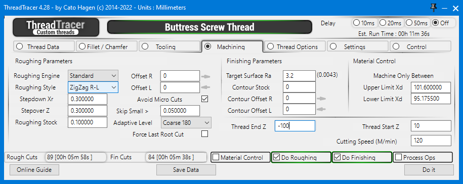
Select Roughing Engine from the dropdown menu.
Standard and Adaptive are available. The standard engine are best suited for thread profiles with flat surfaces.

For threads with more curved surfaces, the adaptive engine gives more control for roughing threads with larger radiuses and leaves a more uniform surface for the finishing passes.
Adaptive Roughing engine works similar to Ridge Height in GibbsCAM mill contouring and will dynamically adapt cut depth for thread passes along any curved surface.
A more in-depth look at the advantages of Adaptive Roughing here : (Adaptive Roughing)

Roughing Engine : Standard Roughing Engine : Adaptive

Roughing Style (Back to top)

Select Roughing Style from the dropdown menu.


Right-Left -- Cycles the roughing passes from right side to left side in the Z direction.
Left-Right -- Cycles the roughing passes from left side to right side in the Z direction.

With Right-Left roughing pattern, tool wear will be concentrated to the bottom-left side of the tool insert. With Left-Right roughing pattern, tool wear wear will be concentrated to the bottom-right side of the tool insert.

Roughing Style : Right-Left Roughing Style : Left-Right

ZigZag R-L -- Cycles the roughing passes in an alternating pattern, first pass in right-left Z direction, then left-right on the next pass.
ZigZag L-R -- Cycles the roughing passes in an alternating pattern, first pass in left-right Z direction, then right-left on the next pass.
A zigzag roughing pattern will distribute tool wear to both edges of the tool insert.

Roughing Style : ZigZag Right-Left Roughing Style : ZigZag Left-Right

Center Out -- Places the first roughing pass in the center of the thread, and cycles the rest of the roughing passes towards the sides.
Center Out can also be useful for remachining an existing thread, as the first center roughing pass can help with alignment when chasing the existing thread.

Sides Only -- This will only do roughing passes along an outline of the thread profile.

Roughing Style : Center Out Roughing Style : Sides Only

Special Roughing Style : CT->Right Side & CT->Left Side (Back to top)

Center->Right Side : This will do roughing passes from the center of the profile towards the right side.
Center->Left Side : This will do roughing passes from the center of the profile towards the left side.

This special roughing style will only rough one half side of the profile and can be used for spesific custom threads that require two seperate tools to complete the thread profile.

Roughing Style : Center->Right Side Roughing Style : Center->Left Side

Special Roughing Style : Right Side->CT & Left Side->CT (Back to top)

Right Side->Center : This will do roughing passes from the right side of the profile towards the center.
Left Side->Center : This will do roughing passes from the left side of the profile towards the center.

This special roughing style will only rough one half side of the profile and can be used for spesific custom threads that require two seperate tools to complete the thread profile.

Roughing Style : Right Side->Center Roughing Style : Left Side->Center

Enable Angle for Center Cuts (Back to top)

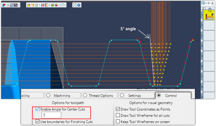
Set an angle for the center stepdown positions to prevent the tool to rub against the same center wall throughout the roughing cycle.
This is set in the Control tab (tab 7)


Roughing Cut Sizes (Back to top)

  • Stepdown Xr : Set the depth of cut for roughing.
  • Stepover Z : Set the width of cut for roughing.
  • Roughing Stock : Set the amount of material to leave for finishing.

  • Roughing Offset (Back to top)

    Offset R and Offset L can be used to offset the roughing passes in the Z axis. Positive and negative numbers.
  • Offset R : This will offset all the roughing cuts on the right side.
  • Offset L : This will offset all the roughing cuts on the left side.
  • For example, setting Offset R to -0.2, will leave 0.2 more material on the right side in addition to the Roughing Stock.

    Avoid Micro Cuts (Back to top)

  • Avoid Micro Cuts : Filters out small roughing cuts based on a threshold.
  • This option will compare the previous depth of cut to the current depth of cut, and if the amount is smaller than a certain amount, it will skip and move to the next roughing cut.
  • Skip Small > : Threshold value used for Avoid Micro Cuts. Any cut size less than entered here will be skipped when generating the roughing cuts.

  • Adaptive Level (Back to top)

  • Adaptive Level : Set the level of detail for adaptive cuts.
  • Default is Coarse and should be sufficient for most cases. It can also give good results with setting a high detail level and keep the 'Avoid Micro Cuts' on.
    A more in-depth look at the advantages of Adaptive Roughing here : (Adaptive Roughing)
    Adaptive Level       : Coarse Adaptive Level       : Fine
    Roughing passes  : 66 Roughing passes  : 109

    Force Last Root Cut (Back to top)

  • Force Last Root Cut : This will force roughing the root of the profile.
  • If there is a tiny amount of material left along the root of the profile, the roughing cycle can often skip this.
    Enabling this will always make roughing cuts along the last portion of the profile.

    Finishing Parameters (Back to top)

  • Target Surface Ra: Set the surface roughness for finishing passes in Ra(µm).
  • Ra is calculated as the Roughness Average of a given surface. Lower Ra number produces higher number of finishing passes, higher Ra number produces less finishing passes.
    If the surface requirement is given in RMS, you need to convert it to Ra(µm).

    The number shown behind 'Target Surface Ra' are the current calculated scallop height with the selected tool and the current distance between passes.

    Common used values :
    Ra 1.6(µm) = Ra 63(µin.) = RMS 64.3
    Ra 3.2(µm) = Ra 125(µin.) = RMS 137.5
    Ra 6.3(µm) = Ra 250(µin.) = RMS 275

    The table below shows comparisons of various surface roughness scales.
    
    	Ra = Roughness Average in micrometers or microinches
    	RMS = Root Mean Square in microinches
    	CLA = Center Line Average in microinches
    	Rt = Roughness Total in microns
    	N = New ISO (grade) scale numbers
    	Cut-off Length = Length required for sample
    
    Use the table if needed and enter required target surface roughness in Ra(micrometers) :

    Contour Stock (Back to top)

  • Contour Stock : Set an amount of stock for finishing passes.

  • Contour Offset (Back to top)

    Contour Offset R and Contour Offset L can be used to offset the finishing passes in the Z axis. Positive and negative numbers.
  • Contour Offset R : This will offset all the finishing passes on the right side of the profile.
  • Contour Offset L : This will offset all the finishing passes on the left side of the profile.
  • These can be used to adjust the width of the profile when finishing.
    Note : Tool Monitoring needs to be turned off (in Control Tab) in order for the tool to go outside the thread profile.

    Material Control (Back to top)

  • Upper Limit Xd : Set the upper limit diameter for both roughing and finishing cuts.
  • Lower Limit Xd : Set the Lower limit diameter for both roughing and finishing cuts.
  • Any cuts outside these limits will be skipped. Use this to control where to machine.

    For example, if you want to run finishing passes for the last 1/3 of the profile, set the Upper Limit to 1/3 of thread height above the Minor Diameter.
    Material Control will only be active if the 'Material Control' is enabled (red outline)

    Material Control will also automatically turn on if any tool is too large to fit the profile. If the tool is too wide to reach the root of the thread, it will allow the tool to go as far as there is space.
    When stopped the Material Control will set the Lower Limit Diameter to where it stopped and ThreadTracer will outline red borders around input boxes that needs to be adjusted.

    Tool too big for the thread profile

    Thread Positions (Back to top)

    Thread End Z : Set where the theading cycle stops.
    Thread Start Z : Set where the theading cycle starts.

    Thread Start Z needs to be minimum one pitch distance outside material.
    If the thread need to start in a thread relief, you can set a Run In in Thread Options tab (Tab 5) to make a smooth entry into the material.

    Cutting Speed for Machining (Back to top)

  • Cutting Speed : The surface cutting speed for machining. The spindle RPM will be calculated based on this value and the diameter of the thread.

  • Auto Clearance in GibbsCAM (link) (Back to top)

    GibbsCAM Clearances from Document Control (inch)


    ThreadTracer uses the Auto Clearance setting in the Document Control window, and will base ENTRY and EXIT approach distances from this.

    Switching Spindle for machining (link) (Back to top)

    Switching Spindle


    To set threading operations to another spindle, select the new spindle in the Part Station dropdown and click Redo. This dropdown are found inside the process window.
    If the operations are not laid out properly, deleting them and create new ones will remember to use the selected spindle in Part Station.

    Control buttons at the bottom (Back to top)

    rough_cut fin_cut material do_rough do_fin process online_guide save_data do_it
    Use the buttons at the bottom of the ThreadTracer dialog to turn on or off actions to make.

    Rough Cuts (Calculated) (Back to top)


    Holds information of the calculated Rough Cuts in the current programmed thread. 'amount of cuts' [ hh:mm:ss ]
    Rough Cuts 60 [ 00h 04m 01s ] means roughing the current programmed thread requires 60 threading passes with an estimated machining time of 4 minutes and 1 seconds.

    Fin Cuts (Calculated) (Back to top)


    Holds information of the calculated Finishing Cuts in the current programmed thread. 'amount of cuts' [ hh:mm:ss ]
    Fin Cuts 112 [ 00h 07m 29s ] means finish machining the current thread requires 112 threading passes with an estimated machining time of 7 minutes and 29 seconds.

    Est. Run Time (Calculated) (Back to top)


    Est. Run Time shows the calculated Run Time for machining, for all Roughing and Finishing passes combined.

    To improve the time estimate, you can set your machine tool Rapid Feedrate in the Settings tab. Your machines rapid feedrate can be found in the parameters of the machine.
    As there are as many rapid moves as feed moves in machining a thread, setting the correct rapid feedrate will allow for a more precise time estimate.

    If you work in metric, set the Rapid Feed in millimeters/minute. If you work in inch, set the Rapid Feed in inches/minute.
    Default values in ThreadTracer are 12000 millimeters/minute for GibbsCAM in metric and 500 inches/minute for GibbsCAM set to inches.


    Material Control ( Checkmark On/Off ) (Back to top)

  • Material Control : This will enable material control, and keep all threading cuts within the set limits. By default the limits are always set to Major and Minor diameter.
  • You can change upper and lower machining limits for Material Control in the Machining Tab.

    Do Roughing ( Checkmark On/Off ) (Back to top)

  • Do Roughing : This will enable roughing of the thread. When enabled it will run the roughing of the selected thread with the set tool parameters when pressing the 'Do It' button.
  • Do Finishing ( Checkmark On/Off ) (Back to top)

  • Do Finishing : This will enable finishing of the thread. When enabled it will run the finishing of the selected thread with the set parameters when pressing the 'Do It' button.
  • Process Ops ( Checkmark On/Off ) (Back to top)

  • Process Ops : This will enable the creation of GibbsCAM threading operations for all the calculated thread coordinates when pressing the 'Do It' button.

  • Do It Button (Back to top)

    Everything in ThreadTracer is controlled by the 'Do It' button.
    You can turn on/off options, generate visual geometry, change cut depths, change tool sizes and everything will be recalculated and updated when you press 'Do It'.
    As long as the 'Process Ops' or 'NC Postprocessor' are disabled, no GibbsCAM operations or g-code will be generated.

    Set up the all the roughing and finishing of the thread and only enable 'Process Ops' when everything seems correct. With 'Process Ops' enabled it will generate GibbsCAM threading operations.
    'Do Roughing' and 'Do Finishing' can be set individually. If only 'Do Finishing' is enabled and 'Process Ops', it will only create GibbsCAM threading operations for the finishing passes.

    Click 'Do It' button to start running the options that's selected.

    As ThreadTracer is an external plugin, there is no 'ReDo' button. If you need to change anything you must delete the threading operations in GibbsCAM and create new ones in ThreadTracer.

    If you delete the threading tool instead, all the operations in GibbsCAM that used that tool will be removed, this is often faster than selecting multiple operations with scrolling for deletion.
    ThreadTracer will always create a new tool based on tools settings from the Tooling tab (Tab 3) if no previous tool exists.

    If you are using NC Tracer to generate g-code for machining, Process Ops should be disabled(off) and instead enable 'NC PostProcessor' in Tab 7.


    Save Data Button (Back to top)

    Click 'Save Data' to store the current thread setup into the GibbsCAM program

    It will create a new data entry if its a new thread, after the thread setup is stored the button will change to 'Update Data'.
    This way you can store and update the same thread entry, and not create a completely new thread entry every time the 'Save Data' is clicked.
    If you need to create a new data entry in the GibbsCAM part, you must close ThreadTracer and restart it, and it will now start with a new data entry.

    With version 4.32 and higher its not necessary to use 'Save' button. All thread data from ThreadTracer are written to each operation and retrievable by using 'Get From Op' button instead.


    These lines of text can also be copied and pasted into other GibbsCAM programs, to quickly recreate the thread without typing in all the parameters again.

    Delay Timer (Back to top)


    Visual Delay Timer for in between each calculated thread pass.
    The Delay Timer can be useful for delaying the visual geometry drawn in GibbsCAM. If something seems off, it can sometimes help track the error with a delay and confirm that every pass is done correctly.
    Delay Timer was initially used in development of ThreadTracer, but kept it as it can be useful to slow things down if there is a suspicion of some passes not being laid out correctly.


    Online Guide Button (Back to top)

    Online Guide button will open this ThreadTracer documentation in a new web browser window.
    ThreadTracer will parse information on what thread style and tab thats currently open, and redirects the web browser to the relevant page.
    Clicking the 'Online Guide' while in Stub Acme and Tab 5, will open the documentation for Stub Acme and Tab 5.

    Advanced Entry & Retract (Link) (Back to top)

    This feature is available in all versions of ThreadTracer v4.35 and up.
    Advanced Entry & Retract allows you to select the placement of the thread on the part using point geometry instead of setting start and end using numbers.

    This can be used for threads that require special placement behind a feature or around an obstacle.

    Advanced Entry
    • Part for threading
    Surface for threading
    Obstacle

    Setup the thread profile and place the thread machining positions outside the part using 'Thread Start Z' and 'Thread End Z'

    Advanced Entry

    Place geometry points to be used as an extended toolpath for the threading cycle. These points can quickly be placed freehand with mouse with using 'Mouse Point' in the Geometry Palette.
    The tool will always start where you placed the thread profile, so place points to guide the tool to the surface on the part.
    For this example, the surface that will be threaded are behind this obstacle so we need to place points to guide the tool around.

    Advanced Entry

    To designate a point to be an entry or retract point, select the point, right-click a point and select "Change feature from "WALL" to "AIR".
    Do this to every point where the tool needs to move in air.

    Advanced Entry
    Entry point 1
    Entry point 2
    Retract point 1
    Retract point 2
    Thread point 1
    Thread point 2
    Thread point 3
    Thread point 4

    By selecting these points in a spesific order, you select the points used for entry, points used for thread surface and points used for retract and return back to start.
    All points that have been set to "AIR" (red) will automatically be set and used as entry and/or retract points by ThreadTracer.

    Points that are normal (yellow) will be used as thread surface.
    Thread point 1 -> 2 will be equivalent to a Run-In angle, therefore you can place Thread point 1 in an angle in relation to Thread point 2.
    Thread point 2 -> 3 will be equivalent to 'Thread Start Z' and 'Thread End Z'.
    Thread point 3 -> 4 will be equivalent to a Run-Out angle.
    Points to be used as thread surface needs to be sets of 4 points.

    All red points selected after normal points (yellow) will automatically be used as retract points by ThreadTracer.

    Select points by holding CTRL key while you click and select the points in the order you want the tool to move.

    Advanced Entry
    1.
    2.
    3.
    4.
    5.
    6.
    7.
    8.

    With the points selected, pressing 'Do It' in ThreadTracer will bring up a window with information about the points.
    The points are automatically sorted and arranged as a new toolpath in the same order as you selected the points.

    Confirm to use the points as a guided toolpath by clicking 'Yes' in the window.

    Advanced Entry

    The new toolpath will be built with colored lines to visually identify the different features.

    Yellow lines represent entry toolpath.
    Green lines represent the toolpath for the actual thread.
    Red lines represent retract moves for the tool (rapid moves).

    Yellow lines will be output as part of the thread, ie tool moves with G32/G33 to keep the tool and spindle in sync.

    Advanced Entry

    The new point based toolpath will stay in memory until you close ThreadTracer or select new points again.
    Generate roughing and finishing operations or adjust parameters for cutting and recreate operations, and it will use the point based toolpath.

    Advanced Entry

    Multiple Thread Surfaces / Synchronized Lefthand & Righthand threads (Back to top)

    To do multiple surfaces for threading, place points in sets of 4 on the part.

    Advanced Entry

    Point 3 and 4 and point 7 and 8 are placed on the minor diameter of the thread.
    Point 2 and 5 and point 6 and 9 are on major diameter.

    Advanced Entry
    1.
    2.
    3.
    4.
    5.
    6.
    7.
    8.
    9.
    10.
    11.

    In this example, we want to machine a synchronized righthand and lefthand rope thread on the part.
    After selecting the point that will run out of the first rightland thread(pt.5), select the entry point for the lefthand thread (pt.6) and select the rest of the points in Z+ direction. (pt 7,8,9)

    If its required for the outer start thread helixes to be oriented equally on the part, start by setting the points 3. and 7. to have a distance relative to the pitch of the thread (whole revolutions).

    If the pitch is 0.5", start with setting the distance between points 3. and 7. to whole revolutions. For example 30 x 0.5 = 15", meaning distance between point 3. and 7. to be 15"

    If the placement of point 3. and 7. needs to be adjusted, translate the points the same amount in each direction.

    Same with the length of the thread surfaces, distance between point 3. and 4. and point 7. and 8. must be identical length.
    Advanced Entry
    1.
    2.
    3.
    4.
    5.
    6.
    7.
    8.
    9.
    10.
    11.

    Confirm to use the points as a guided toolpath by clicking 'Yes' in the window.

    Advanced Entry


    Advanced Entry


    Advanced Entry


    Page accessed : 624 times