ThreadTracer Online Documentation ThreadTracer for GibbsCAM
header_logo
© 2014-2024 Cato Hagen
ThreadTracer

Home Features Documentation Media Updates Download Purchase Resellers
Additional Plugins

MillTracer MillBlunt WaveThread Other Plugins

Customer Login

Login or Register
Contact

Contact Info
ThreadTracer 4 - Online Guide   Switching Spindle Auto ClearanceAdvanced Entry & Retract      

   Use mouse and click in the interface to jump down to the relevant section for any spesific element ( tabs,buttons or options )
FREEFORM FREEFORM FREEFORM FREEFORM FREEFORM FREEFORM FREEFORM enable_blunt_start stepdown_xr stepover_z blunt_revolutions spindle_rpm run_out_angle run_in_angle height to remove mach style offset exit cut run in out taper full profile exit delay est_runtime rough_cut fin_cut material do_rough do_rough process online_guide save_data do_it

Freeform Thread \\ Thread Options (Tab 5):

Bluntstart / Quickstart parameters (Back to top)

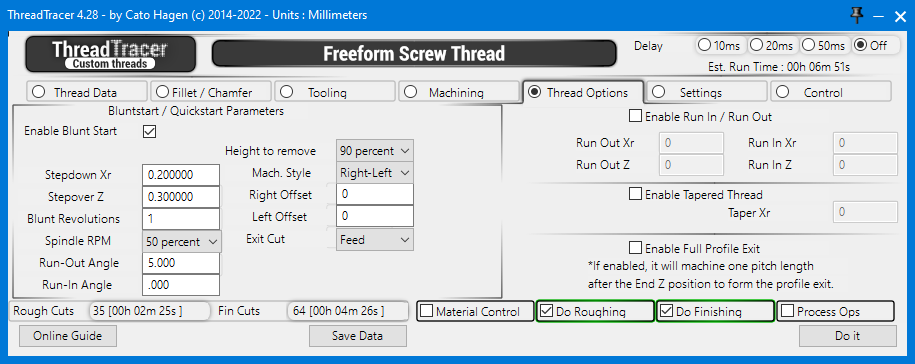
Automatically apply Blunt Start / Quick Start threads. For removal of incomplete threads on the part.

Bluntstart / Quickstart
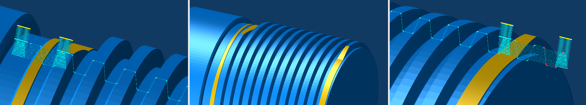
Removal of incomplete thread at the end of a thread Removal of incomplete thread at both ends of a thread Removal of incomplete thread at the front of a thread

Enable Blunt Start (Back to top)

Enable Blunt Start : This will enable Blunt Start threads to be calculated when pressing the Do It button. All machining will be done with the same tool as the main thread ( as defined in Tooling tab ).
It can be a good practice to set up the main thread first and generate the operations for roughing and finishing, then turn off Do Roughing and Do Finishing and apply the operations for blunting seperately.

Remember to turn on Process Ops to generate GibbsCAM operations for blunt start. Turn Process Ops off while setting everything up.
For Blunt starts in multiple positions on the thread, GibbsCAM operations for one position must be generated at a time.

Stepdown Xr ( Blunt ) (Back to top)

Stepdown Xr : Set the depth of cut for all blunting passes.

Stepover Z ( Blunt ) (Back to top)

Stepover Z : Set the width of cut for blunting passes.

Blunt Revolutions (Back to top)

Set the amount of revolutions of thread to remove. This is calculated from Thread Start Z in Machining tab (Tab 4)
Depending of how far the Thread Start Z are set from the material, set any number here until it reaches over the incomplete thread.
Use number with decimal to adjust in between revolutions e.g. 1.5 or 2.2

blunt_revolutions
Blunt Revolutions : 1 Blunt Revolutions : 2

Spindle RPM ( Blunt ) (Back to top)

Spindle RPM : Set to use 100% or 50% RPM for when machining blunting passes.
100% will use the same RPM as the roughing passes, 50% will use half the RPM as the roughing passes.

If the machine can handle changing RPM and be synchronized, a lower RPM can help the machine to perform these short and fast moving threading toolpaths.

DIfferent machine vendors have this as a seperate option to change RPM during threading and keep the thread synchronized. If your machine are not equipped with this, use Spindle RPM at 100%

Run-Out Angle ( Blunt ) (Back to top)

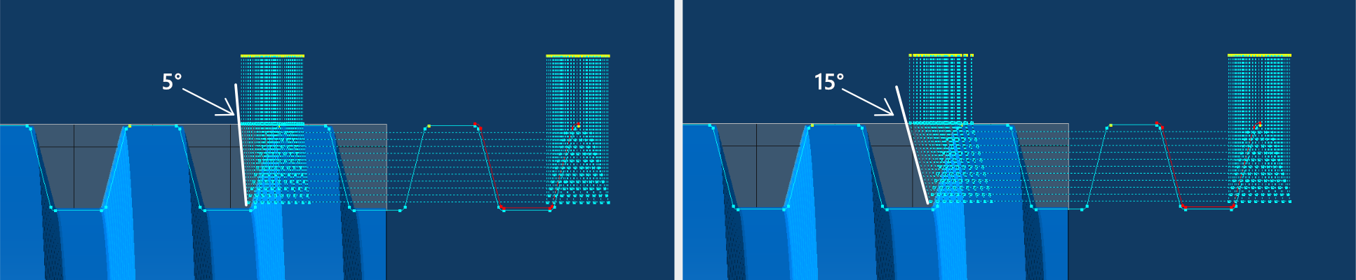
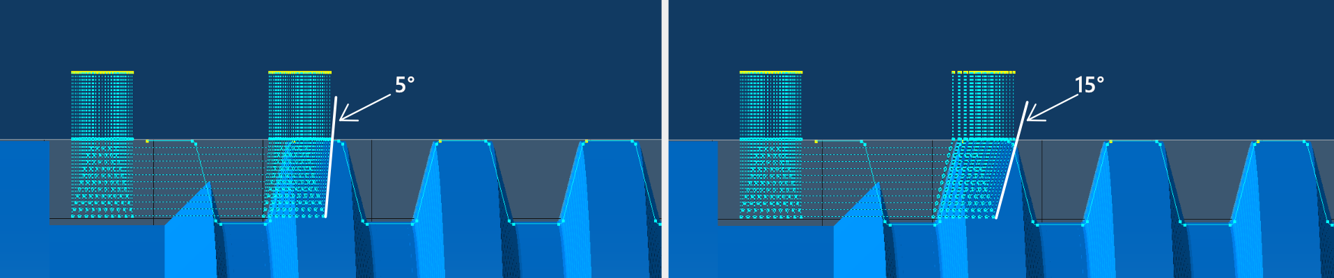
Set an run-out angle for the tool to exit the material. 0 is straight up and will produce the shortest blunt.
Larger angle will make the tool to use longer time to move out of the material so the distance of the blunted thread will be longer.

Run-Out Angle are not necessary for when exiting into a thread relief or air, as when making a blunted thread at the end of the thread.

Draw Tool Coordinates
Run-Out Angle : 5° Run-Out Angle : 15°

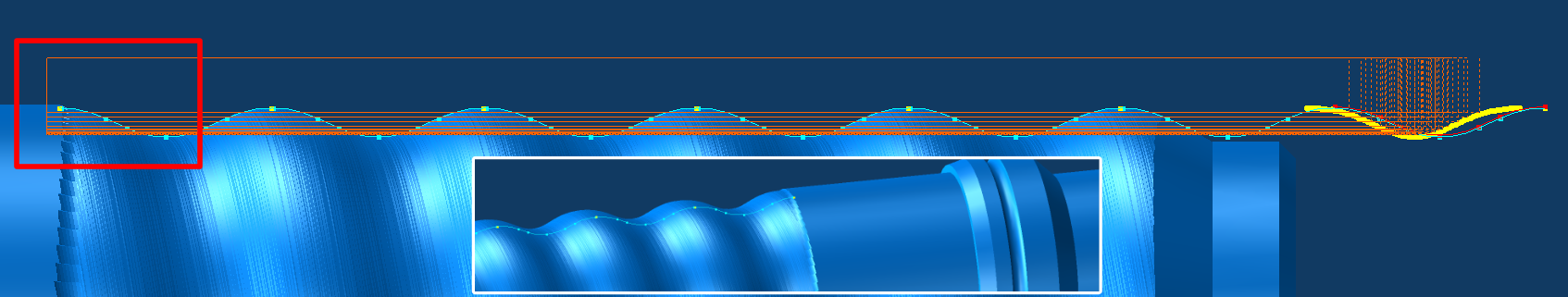
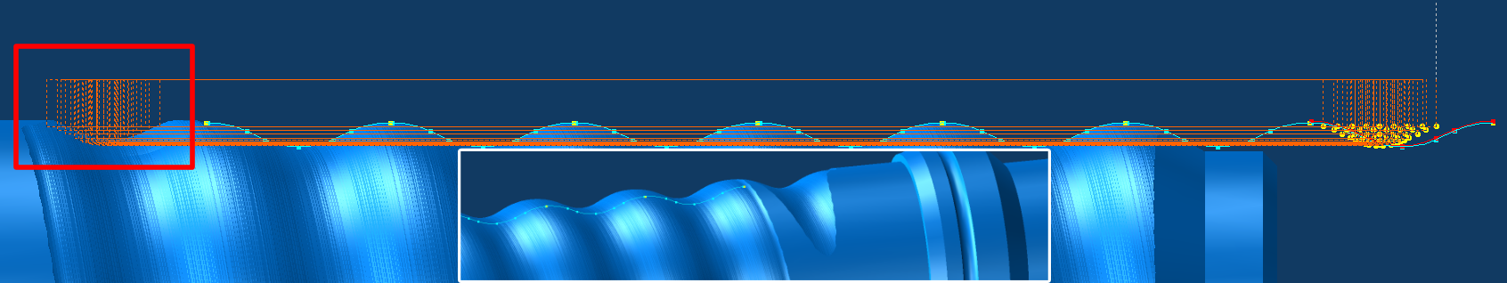
Simulation with Blunt/Quickstart at the start of the thread, 5° and 15° Run-Out Angle


Run-In Angle ( Blunt ) (Back to top)

Set an run-in angle for the tool when entering material. 0 is straight down and should only be used if starting in air.
Larger angle will make the tool to use longer time to reach the cut depth so the distance of the blunted thread will be longer.

Run-In Angle are not necessary for entry into air, as when making a blunted thread at the start of the thread.

Draw Tool Coordinates
Run-In Angle : 5° Run-In Angle : 15°

Simulation with Blunt/Quickstart at the end of the thread, 5° and 15° Run-In Angle


Height to remove ( Blunt ) (Back to top)

  • Height to remove : Set the percentage of thread height to remove. 100% will remove the thread down to the root. 90% will leave a tiny amount and often results in a better finish.
  •       Select from the dropdown menu what percentage of thread height to remove. 50%, 60%, 70%, 80%, 90%, 95% and 100% are available.


    Machining Style for Blunting (Back to top)

  • Mach Style : Select machining style for blunting.
  • - Right-Left : Cycles the blunting cuts from right side to left side in the Z direction.
  • - Left-Right : Cycles the blunting cuts from left side to right side in the Z direction.
  • - ZigZag R-L : Cycles the blunting cuts in an alternating pattern, first pass in right-left Z direction, then left-right on the next pass.
  • - ZigZag L-R : Cycles the blunting cuts in an alternating pattern, first pass in left-right Z direction, then right-left on the next pass.
  • - Center Out : Places the first blunting pass in the center of the thread, and cycles the blunting cuts towards the sides.
  • - Sides Only : This will only do blunting passes along the outside of the thread profile.

  • Offsets ( Blunt ) (Back to top)

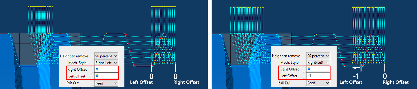
    Right Offset and Left Offset can be used to offset the blunt position in the Z axis. Use positive and negative numbers for both directions.

    Right Offset : This will offset the blunting positions on the right side of the thread profile.
    Left Offset : This will offset the blunting positions on the left side of the thread profile.

    The default Right and Left offsets of 0 are the calculated minimum width and position the current tool need to remove the thread down to the root.
    Various machine tool states with different parameters, ballscrew backlash, acceleration settings, etc can make different machines leave different results when blunting threads.

    When running these blunt passes for the first time, always try to run with conservative depth of cuts and observe the machining process.
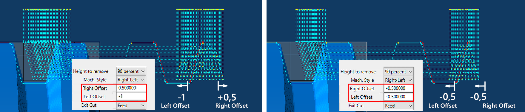
    If the tool leaves a sliver of thread after the process, you can adjust and center the blunt toolpath with Right and Left offsets.

    Widen the cutting area with adjusting Right and Left offsets in opposite directions (± Z axis).
    Move the cutting area with adjusting Right and Left offsets in the same directions (± Z axis).

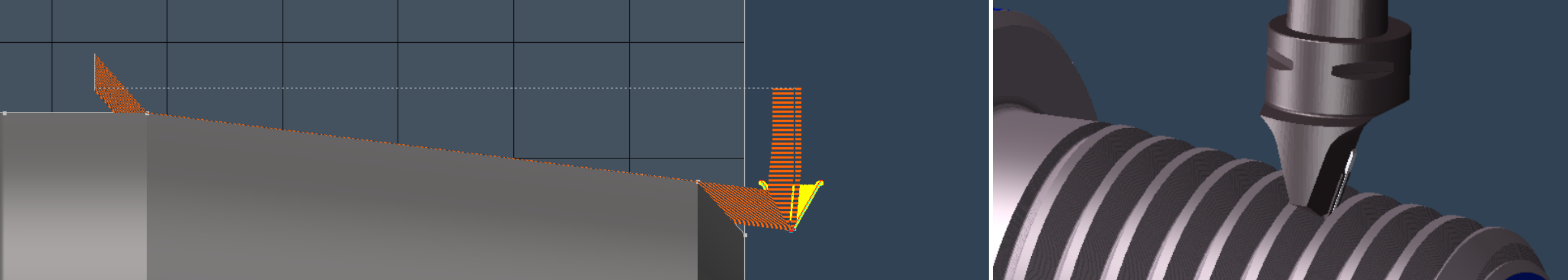
    When setting up this can be useful to turn on Draw Toolpath Lines under Control tab to visualize the toolpaths before creating GibbsCAM operations (See image below).
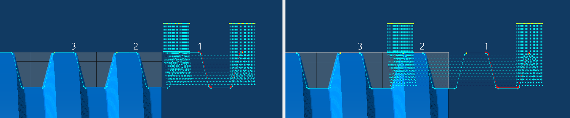
    blunt_offsets_01
    Blunt Offsets
    blunt_offsets_01
    Blunt Offsets

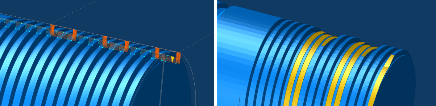
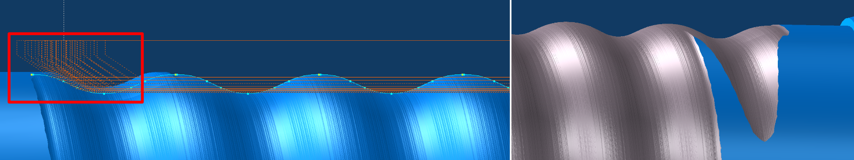
    With moving the blunt positions towards the end of the thread, you can machine away the sharp portion at the end of the thread.

    Move the blunt position by counting the number of threads / revolutions and multiply this with the pitch of the thread.
    Lets say for 15 threads / revolutions on a 4 TPI thread, set both Right Offset and Left Offset to -15*6.35 (-95.25mm) or if you work in inches, -15*0.25 (-3.75in)

    You can enter mathematical operations directly in all the input boxes, e.g. type -15*6.35 and hit Tab key on keyboard.


    Move positions anywhere on the thread, offset the position with multiplying revolutions with the pitch of the thread, and amount of revolutions to remove.

    blunt_offsets_01
    Removing portions of a thread in multiple positions

    Always remember to use Run-in angle when moving blunting into the thread. Without Run-in all the blunt cuts will rapid unsynchronized into the thread.


    Exit Cut ( Blunt ) (Back to top)

    Exit Cut : Set feed exit or rapid exit for when exiting out of the thread. Setting this to rapid will use G0 for exiting out of the thread.

    Feed Exit will move the tool out of material with the same feed as when threading and follow the set Run-Out angle. Run-Out angle will determine the length of the blunted thread.
    Rapid exit will move the tool out of material with rapid feedrate and will produce a short and steep blunted thread.


    Run In / Run Out ( Thread ) (Back to top)

  • Enable Run In / Run Out : This will enable to use a run in and run out for the threading passes.
  • Run Out Xr : Set the amount for run out [X axis]
  • Run Out Z : Set the amount for run out [Z axis]
  • Run In Xr : Set the amount for run in [X axis]
  • Run In Z : Set the amount for run in [Z axis]

  • Tapered Thread ( Thread ) (Back to top)

  • Enable Tapered Thread : This will enable a taper on the thread.
  • Taper Xr : Set the decimal Xr slope. An NPT thread has a slope of 1/32 per side.

  • tapered_thread_01
    Tapered Thread - API style

    Full Profile Exit ( Thread ) (Back to top)

    With Full Profile Exit option enabled, it will extend the end position past Thread End Z to follow the thread profile out of material.
    With using Full Profile Exit, the exit of the thread will look similar to as if the thread was machined with a tool with the same profile as the thread.

    This can also be used if the thread have no relief groove, and will produce a smoother end transition to the thread.

    full_profile_01
    Full Profile Exit - OFF

    full_profile_01
    Full Profile Exit - ON

    full_profile_01
    Full Profile Exit - ON & Run Out


    Control buttons at the bottom (Back to top)

    rough_cut fin_cut material do_rough do_fin process online_guide save_data do_it
    Use the buttons at the bottom of the ThreadTracer dialog to turn on or off actions to make.

    Rough Cuts (Calculated) (Back to top)


    Holds information of the calculated Rough Cuts in the current programmed thread. 'amount of cuts' [ hh:mm:ss ]
    Rough Cuts 60 [ 00h 04m 01s ] means roughing the current programmed thread requires 60 threading passes with an estimated machining time of 4 minutes and 1 seconds.

    Fin Cuts (Calculated) (Back to top)


    Holds information of the calculated Finishing Cuts in the current programmed thread. 'amount of cuts' [ hh:mm:ss ]
    Fin Cuts 112 [ 00h 07m 29s ] means finish machining the current thread requires 112 threading passes with an estimated machining time of 7 minutes and 29 seconds.

    Est. Run Time (Calculated) (Back to top)


    Est. Run Time shows the calculated Run Time for machining, for all Roughing and Finishing passes combined.

    To improve the time estimate, you can set your machine tool Rapid Feedrate in the Settings tab. Your machines rapid feedrate can be found in the parameters of the machine.
    As there are as many rapid moves as feed moves in machining a thread, setting the correct rapid feedrate will allow for a more precise time estimate.

    If you work in metric, set the Rapid Feed in millimeters/minute. If you work in inch, set the Rapid Feed in inches/minute.
    Default values in ThreadTracer are 12000 millimeters/minute for GibbsCAM in metric and 500 inches/minute for GibbsCAM set to inches.


    Material Control ( Checkmark On/Off ) (Back to top)

  • Material Control : This will enable material control, and keep all threading cuts within the set limits. By default the limits are always set to Major and Minor diameter.
  • You can change upper and lower machining limits for Material Control in the Machining Tab.

    Do Roughing ( Checkmark On/Off ) (Back to top)

  • Do Roughing : This will enable roughing of the thread. When enabled it will run the roughing of the selected thread with the set tool parameters when pressing the 'Do It' button.
  • Do Finishing ( Checkmark On/Off ) (Back to top)

  • Do Finishing : This will enable finishing of the thread. When enabled it will run the finishing of the selected thread with the set parameters when pressing the 'Do It' button.
  • Process Ops ( Checkmark On/Off ) (Back to top)

  • Process Ops : This will enable the creation of GibbsCAM threading operations for all the calculated thread coordinates when pressing the 'Do It' button.

  • Do It Button (Back to top)

    Everything in ThreadTracer is controlled by the 'Do It' button.
    You can turn on/off options, generate visual geometry, change cut depths, change tool sizes and everything will be recalculated and updated when you press 'Do It'.
    As long as the 'Process Ops' or 'NC Postprocessor' are disabled, no GibbsCAM operations or g-code will be generated.

    Set up the all the roughing and finishing of the thread and only enable 'Process Ops' when everything seems correct. With 'Process Ops' enabled it will generate GibbsCAM threading operations.
    'Do Roughing' and 'Do Finishing' can be set individually. If only 'Do Finishing' is enabled and 'Process Ops', it will only create GibbsCAM threading operations for the finishing passes.

    Click 'Do It' button to start running the options that's selected.

    As ThreadTracer is an external plugin, there is no 'ReDo' button. If you need to change anything you must delete the threading operations in GibbsCAM and create new ones in ThreadTracer.

    If you delete the threading tool instead, all the operations in GibbsCAM that used that tool will be removed, this is often faster than selecting multiple operations with scrolling for deletion.
    ThreadTracer will always create a new tool based on tools settings from the Tooling tab (Tab 3) if no previous tool exists.

    If you are using NC Tracer to generate g-code for machining, Process Ops should be disabled(off) and instead enable 'NC PostProcessor' in Tab 7.


    Save Data Button (Back to top)

    Click 'Save Data' to store the current thread setup into the GibbsCAM program

    It will create a new data entry if its a new thread, after the thread setup is stored the button will change to 'Update Data'.
    This way you can store and update the same thread entry, and not create a completely new thread entry every time the 'Save Data' is clicked.
    If you need to create a new data entry in the GibbsCAM part, you must close ThreadTracer and restart it, and it will now start with a new data entry.

    With version 4.32 and higher its not necessary to use 'Save' button. All thread data from ThreadTracer are written to each operation and retrievable by using 'Get From Op' button instead.


    These lines of text can also be copied and pasted into other GibbsCAM programs, to quickly recreate the thread without typing in all the parameters again.

    Delay Timer (Back to top)


    Visual Delay Timer for in between each calculated thread pass.
    The Delay Timer can be useful for delaying the visual geometry drawn in GibbsCAM. If something seems off, it can sometimes help track the error with a delay and confirm that every pass is done correctly.
    Delay Timer was initially used in development of ThreadTracer, but kept it as it can be useful to slow things down if there is a suspicion of some passes not being laid out correctly.


    Online Guide Button (Back to top)

    Online Guide button will open this ThreadTracer documentation in a new web browser window.
    ThreadTracer will parse information on what thread style and tab thats currently open, and redirects the web browser to the relevant page.
    Clicking the 'Online Guide' while in Stub Acme and Tab 5, will open the documentation for Stub Acme and Tab 5.

    Advanced Entry & Retract (Link) (Back to top)

    This feature is available in all versions of ThreadTracer v4.35 and up.
    Advanced Entry & Retract allows you to select the placement of the thread on the part using point geometry instead of setting start and end using numbers.

    This can be used for threads that require special placement behind a feature or around an obstacle.

    Advanced Entry
    • Part for threading
    Surface for threading
    Obstacle

    Setup the thread profile and place the thread machining positions outside the part using 'Thread Start Z' and 'Thread End Z'

    Advanced Entry

    Place geometry points to be used as an extended toolpath for the threading cycle. These points can quickly be placed freehand with mouse with using 'Mouse Point' in the Geometry Palette.
    The tool will always start where you placed the thread profile, so place points to guide the tool to the surface on the part.
    For this example, the surface that will be threaded are behind this obstacle so we need to place points to guide the tool around.

    Advanced Entry

    To designate a point to be an entry or retract point, select the point, right-click a point and select "Change feature from "WALL" to "AIR".
    Do this to every point where the tool needs to move in air.

    Advanced Entry
    Entry point 1
    Entry point 2
    Retract point 1
    Retract point 2
    Thread point 1
    Thread point 2
    Thread point 3
    Thread point 4

    By selecting these points in a spesific order, you select the points used for entry, points used for thread surface and points used for retract and return back to start.
    All points that have been set to "AIR" (red) will automatically be set and used as entry and/or retract points by ThreadTracer.

    Points that are normal (yellow) will be used as thread surface.
    Thread point 1 -> 2 will be equivalent to a Run-In angle, therefore you can place Thread point 1 in an angle in relation to Thread point 2.
    Thread point 2 -> 3 will be equivalent to 'Thread Start Z' and 'Thread End Z'.
    Thread point 3 -> 4 will be equivalent to a Run-Out angle.
    Points to be used as thread surface needs to be sets of 4 points.

    All red points selected after normal points (yellow) will automatically be used as retract points by ThreadTracer.

    Select points by holding CTRL key while you click and select the points in the order you want the tool to move.

    Advanced Entry
    1.
    2.
    3.
    4.
    5.
    6.
    7.
    8.

    With the points selected, pressing 'Do It' in ThreadTracer will bring up a window with information about the points.
    The points are automatically sorted and arranged as a new toolpath in the same order as you selected the points.

    Confirm to use the points as a guided toolpath by clicking 'Yes' in the window.

    Advanced Entry

    The new toolpath will be built with colored lines to visually identify the different features.

    Yellow lines represent entry toolpath.
    Green lines represent the toolpath for the actual thread.
    Red lines represent retract moves for the tool (rapid moves).

    Yellow lines will be output as part of the thread, ie tool moves with G32/G33 to keep the tool and spindle in sync.

    Advanced Entry

    The new point based toolpath will stay in memory until you close ThreadTracer or select new points again.
    Generate roughing and finishing operations or adjust parameters for cutting and recreate operations, and it will use the point based toolpath.

    Advanced Entry

    Multiple Thread Surfaces / Synchronized Lefthand & Righthand threads (Back to top)

    To do multiple surfaces for threading, place points in sets of 4 on the part.

    Advanced Entry

    Point 3 and 4 and point 7 and 8 are placed on the minor diameter of the thread.
    Point 2 and 5 and point 6 and 9 are on major diameter.

    Advanced Entry
    1.
    2.
    3.
    4.
    5.
    6.
    7.
    8.
    9.
    10.
    11.

    In this example, we want to machine a synchronized righthand and lefthand rope thread on the part.
    After selecting the point that will run out of the first rightland thread(pt.5), select the entry point for the lefthand thread (pt.6) and select the rest of the points in Z+ direction. (pt 7,8,9)

    If its required for the outer start thread helixes to be oriented equally on the part, start by setting the points 3. and 7. to have a distance relative to the pitch of the thread (whole revolutions).

    If the pitch is 0.5", start with setting the distance between points 3. and 7. to whole revolutions. For example 30 x 0.5 = 15", meaning distance between point 3. and 7. to be 15"

    If the placement of point 3. and 7. needs to be adjusted, translate the points the same amount in each direction.

    Same with the length of the thread surfaces, distance between point 3. and 4. and point 7. and 8. must be identical length.
    Advanced Entry
    1.
    2.
    3.
    4.
    5.
    6.
    7.
    8.
    9.
    10.
    11.

    Confirm to use the points as a guided toolpath by clicking 'Yes' in the window.

    Advanced Entry


    Advanced Entry


    Advanced Entry


    Page accessed : 350 times