ThreadTracer Online Documentation ThreadTracer for GibbsCAM
header_logo
© 2014-2024 Cato Hagen
ThreadTracer

Home Features Documentation Media Updates Download Purchase Resellers
Additional Plugins

MillTracer MillBlunt WaveThread Other Plugins

Customer Login

Login or Register
Contact

Contact Info
ThreadTracer 4 - Online Guide   Switching Spindle Auto ClearanceAdvanced Entry & Retract      

   Use mouse and click in the interface to jump down to the relevant section for any spesific element ( tabs,buttons or options )
FREEFORM FREEFORM FREEFORM FREEFORM FREEFORM FREEFORM FREEFORM import switch type repair nc post toolpath options Boundaries for Finishing Cuts Add Finish cuts over Crest flats Custom Finishing Order tool monitor nested wave chipbreak wave chipbreak parameters tool_coordinates_as_points tool_wireframe_for_all_cuts keep_tool_wireframe texual_thread_data profile_over_whole_thread stock_as_red_geometry tool_gouges_as_red_wireframe toolpath_lines delay est_runtime rough_cut fin_cut material do_rough do_rough process online_guide save_data do_it

Freeform Thread \\ Control (Tab 7):

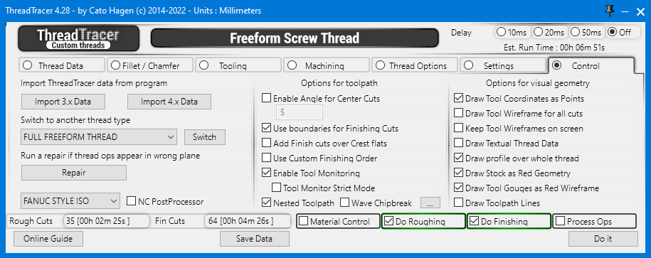
Import ThreadTracer data from current open GibbsCAM program (Back to top)


All the parameters and settings for a thread setup can be stored inside the GibbsCAM file, this allows for loading back the same setup into ThreadTracer if you want to change something later.
  • Import 3.x Data : This button will check for thread setups made with ThreadTracer 3.x.
  • Import 4.x Data : This button will check for thread setups made with ThreadTracer 4.x.
  • If any are found they will be presented and you can choose to load them back.

    Switch to another thread type (Back to top)

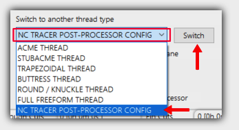
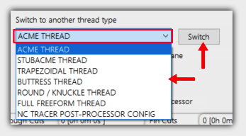
    Choose what thread type to make from the dropdown list.
  • Switch : Clicking this button will switch the thread setup to the one selected from the dropdown.

  • Run a repair if thread ops appear in wrong plane (Back to top)

    If the threading operations are made in the wrong plane, clicking the 'Repair' button will try to restore the GibbsCAM threading dialog to a working state.
    If a repair has been done, all the current threading operations needs to be deleted and redone.


    NC Tracer Post Processor (Back to top)

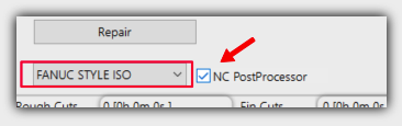
  • NC Postprocessor : Enable this to post the current thread with the internal post processor.
  • .
    You can select what machine configuration to post for in the dropdown list.
    The machine configurations can be edited with selecting 'NC TRACER POST PROCESSOR CONFIG' as thread type and pressing the 'Switch' button.

    If you post with the internal post processor, it will ask where to save the NC-code file and open the file in Notepad.exe when its done.
    You can also configure NC Tracer to paste the NC-code directly to the clipboard, and paste it directly to your preferred editor.
    To read on how to setup NC Tracer for your machine, click here : Nc Tracer Setup

    Options for toolpath (Back to top)

    Enable Angle for Center cuts (Back to top)

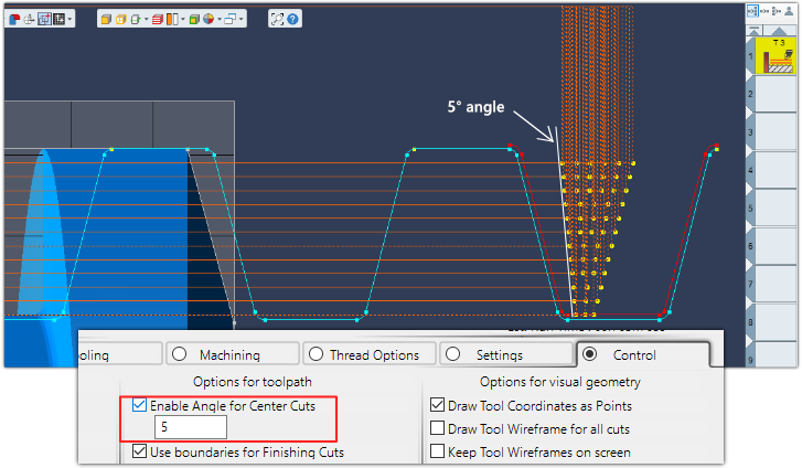
    Used for roughing cuts, and if using one of the Special Roughing Style, as CT->Right Side, CT->Left Side, Right Side->CT or Left Side->CT
    Will use an angle for the center stepdown positions to prevent the tool to rub against the same sidewall throughout the cycle.


    Boundaries for Finishing Cuts (Back to top)

    Use boundaries for Finishing Cuts : This should always be enabled for safety.
    When calculating finishing passes, it will only follow the geometry of the thread profile without checking distance to neighboring profile geometry.
    This will first scan through the thread profile and calculate internal boundaries for all the finishing passes.

    Add Finish cuts over Crest flats (Back to top)

  • Add Finish cuts over Crest flats : This will add finishing cuts over the crest of the thread profile.
    This can be useful for threads with tight tolerances as all surfaces will be relative to the same tool offset.

  • Use Custom Finishing Order (Back to top)

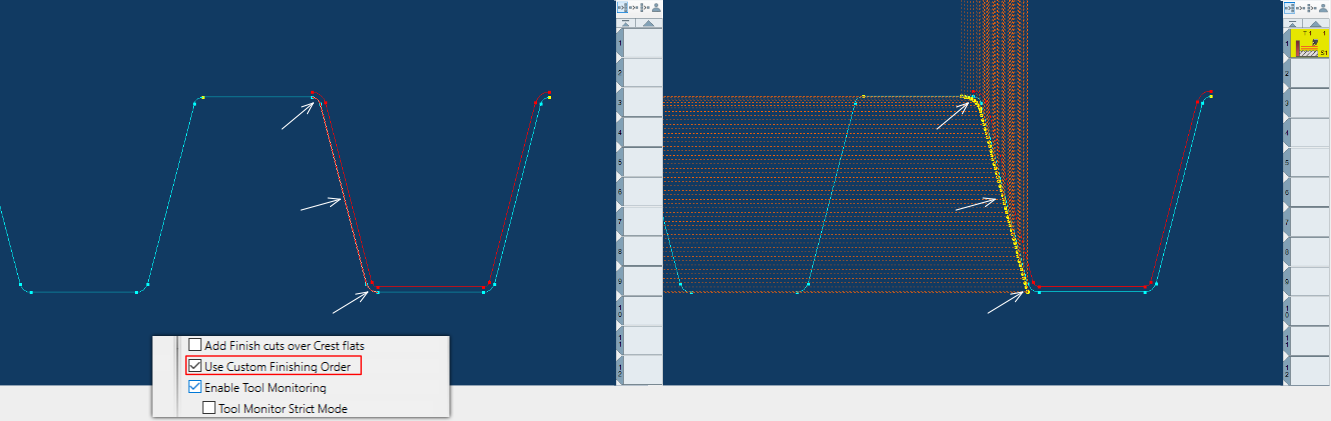
    Enable this to select what features to run finishing passes on. The finishing passes will run on the features selected on the thread profile geometry.
    Select individual features with holding CTRL button and select with the the mousepointer.

    This can be useful for a large thread where you only need to re-run finishing on selected features to save some machining time.

    Draw Tool Coordinates
    • Select features of the thread you want to finish.
    • Enable 'Use Custom Finishing Order' in the Control tab
    • Clicking 'Do It' will generate finishing for selected geometry only


    Enable Tool Monitoring (Back to top)

    Enable this to monitor the insert geometry against the thread flank walls or sides.
    If the sides of the insert gouges or crosses the thread profile, it will trigger an alert and not output or generate threading operations. The insert profile will be drawn in red if alert is triggered.

    Note : False positives might occur due to small mathematical rounding errors, disable Tool Monitor if you can visually confirm that the tool clears the profile correctly.

    Tool Monitor Strict Mode (Back to top)
    This will monitor the thread flank walls upto the crest diameter, and ignore the crest corner radius or chamfer.

    • Ratchet thread and VBMT insert that gouges thread profile
    • Ratchet thread and VBMT insert pointing down, no gouges
    • Acme thread and VBMT insert that gouges thread profile

    Nested Toolpath (Back to top)

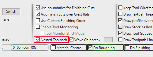
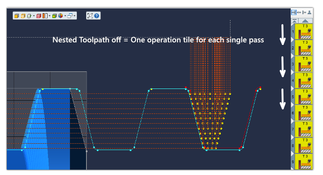
    Nested Toolpath option will combine all roughing passes or finishing passes into a single threading operation.
    A Nested Toolpath looks similar as a normal threading operation in GibbsCAM and uses only one operation tile.
    It will seperate roughing and finishing into each seperate operation tiles. As any nested toolpath is built internally by ThreadTracer, you cannot Redo these operations in GibbsCAM.


    Wave Chipbreaker (Back to top)

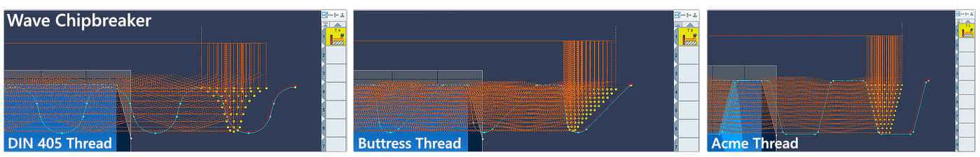
    For machining threads in long-chipping materials, like different plastics, titanium, aluminum and some steel alloys.

    Wave Chipbreaker can be used on any thread and will apply oscillating movements to the X axis while threading as an attempt to break up long strings of chips.

    Advantage is preventing long strings of chips to coil around the chuck, tools or the part. Disadvantage is longer machining time, as these oscillating thread passes needs a straight cleanup pass.
    For automated machining solutions, good chip control is critical for a reliable process. Picking up a part with a robot or a sub spindle in the machine can cause problems if long strings of chips are curled around the part.
    Wave Chipbreaker can solve problems with chip control in scenarios like this and can help the process to be accurate and more reliable.

    Wave Chipbreaker was inspired from Sandvik Coromant OptiThreading™ - a new software module in their CoroPlus Tool Path.
    All credit to Sandvik Coromant for coming up with this method for chip control. Read about OptiThreading™ here.

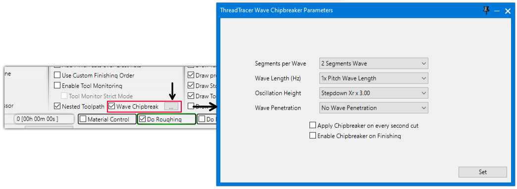
    Wave Chipbreaker is only available when using Nested Toolpath.


    Wave Chipbreaker thread pass with a following straight cleanup pass


    Machining 4-TPI thread with a 2mm grooving tool. Top corner shows NC-code running while machining.

    Wave Chipbreaker Parameters (Back to top)

    Edit parameters for Wave Chipbreaker with clicking the button with 3 dots [...] A seperate window will open where you can set different parameters.

    Click on the image and on items in the Wave Parameter window to jump to the relevant section of documentation. (Or just scroll...)

    wave_chipbreak_segments wave_chipbreak_length wave_chipbreak_oscillation wave_chipbreak_penetration wave_chipbreak_every_second wave_chipbreak_finish

    Wave Segments (Back to top) (Back to Wave Parameters)

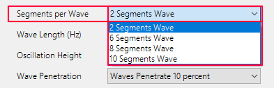
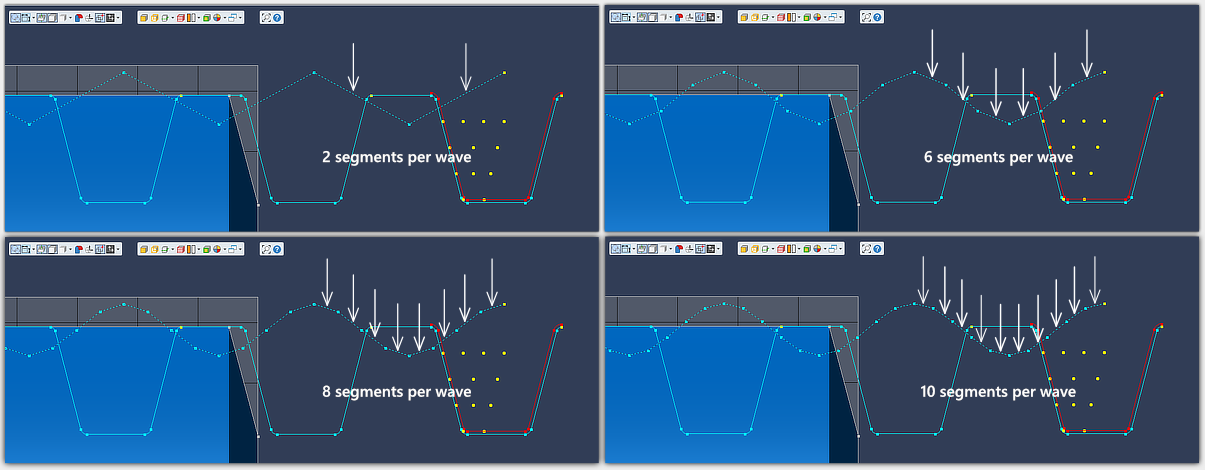
    Set the amount of segments per wave. 2 segments produce a saw tooth wave and requires the least amount of lines in the NC-code.
    More segments produces a more detailed wave and requires more lines in the NC-code to complete the wave.
    See example NC-code below for difference between 2 segments and 6 segments (Expandable buttons).


    Click the buttons below to expand and display example NC-code snippets for differences between 2 and 6 segment wave.
    This is NC-code posted with the internal post-processor in ThreadTracer. GibbsCAM post-processors will output same NC-code coordinates for threading.
    			
    ( THREADTRACER V4.28 -> NC-TRACER G-CODE )
    ( MACHINE, FANUC STYLE ISO )
    ( THREAD STYLE, ACME )
    ( --------- EXTERNAL THREAD --------- )
    ( MAJOR/MINOR DIA : 101.44125 / 94.22765 MM )
    ( TPI, 4 PITCH, 6.35 MM )
    ( THREAD HEIGHT, 3.6068 FLAT ROOT, 2.275 )
    ( RADIUS, 0.2127 RADIUS, 0.1588 )
    ...
    G0 Z7.866
    G0 X100.857
    G0 X107.441 ( WAVE CHIPBREAK CUT # 1)
    G0 X102.026 
    G32 X100.857 Z4.691 F6.35
    G32 X102.026 Z1.516 F6.35
    G32 X100.857 Z-1.659 F6.35
    G32 X102.026 Z-4.834 F6.35
    G32 X100.857 Z-8.009 F6.35
    G32 X102.026 Z-11.184 F6.35
    G32 X100.857 Z-14.359 F6.35
    G32 X102.026 Z-17.534 F6.35
    G32 X100.857 Z-20.709 F6.35
    G32 X102.026 Z-23.884 F6.35
    G32 X100.857 Z-27.059 F6.35
    G32 X102.026 Z-30.234 F6.35
    G32 X100.857 Z-33.409 F6.35
    G32 X102.026 Z-36.584 F6.35
    G32 X100.857 Z-39.759 F6.35
    G32 X102.026 Z-42.934 F6.35
    G32 X100.857 Z-46.109 F6.35
    G32 X102.026 Z-49.284 F6.35
    G0 X107.441 ( PART CLEARANCE )
    G0 Z7.866
    G0 X100.857
    G32 X100.857 Z-50 F6.35
    G0 X107.441 ( PART CLEARANCE )
    ( CUT # 2 OF 134 TOTAL )
    G0 Z7.492
    ...


    ( THREADTRACER V4.28 -> NC-TRACER G-CODE )
    ( MACHINE, FANUC STYLE ISO )
    ( THREAD STYLE, ACME )
    ( --------- EXTERNAL THREAD --------- )
    ( MAJOR/MINOR DIA : 101.44125 / 94.22765 MM )
    ( TPI, 4 PITCH, 6.35 MM )
    ( THREAD HEIGHT, 3.6068 FLAT ROOT, 2.275 )
    ( RADIUS, 0.2127 RADIUS, 0.1588 )
    ...
    G0 Z7.866
    G0 X100.857
    G0 X107.441 ( WAVE CHIPBREAK CUT # 1)
    G0 X102.026 
    G32 X101.734 Z6.808 F6.35
    G32 X101.149 Z5.749 F6.35
    G32 X100.857 Z4.691 F6.35
    G32 X101.149 Z3.633 F6.35
    G32 X101.734 Z2.574 F6.35
    G32 X102.026 Z1.516 F6.35
    G32 X101.734 Z0.458 F6.35
    G32 X101.149 Z-0.601 F6.35
    G32 X100.857 Z-1.659 F6.35
    G32 X101.149 Z-2.717 F6.35
    G32 X101.734 Z-3.776 F6.35
    G32 X102.026 Z-4.834 F6.35
    G32 X101.734 Z-5.892 F6.35
    G32 X101.149 Z-6.951 F6.35
    G32 X100.857 Z-8.009 F6.35
    G32 X101.149 Z-9.067 F6.35
    G32 X101.734 Z-10.126 F6.35
    G32 X102.026 Z-11.184 F6.35
    G32 X101.734 Z-12.242 F6.35
    G32 X101.149 Z-13.301 F6.35
    G32 X100.857 Z-14.359 F6.35
    G32 X101.149 Z-15.417 F6.35
    G32 X101.734 Z-16.476 F6.35
    G32 X102.026 Z-17.534 F6.35
    G32 X101.734 Z-18.592 F6.35
    G32 X101.149 Z-19.651 F6.35
    G32 X100.857 Z-20.709 F6.35
    G32 X101.149 Z-21.767 F6.35
    G32 X101.734 Z-22.826 F6.35
    G32 X102.026 Z-23.884 F6.35
    G32 X101.734 Z-24.942 F6.35
    G32 X101.149 Z-26.001 F6.35
    G32 X100.857 Z-27.059 F6.35
    G32 X101.149 Z-28.117 F6.35
    G32 X101.734 Z-29.176 F6.35
    G32 X102.026 Z-30.234 F6.35
    G32 X101.734 Z-31.292 F6.35
    G32 X101.149 Z-32.351 F6.35
    G32 X100.857 Z-33.409 F6.35
    G32 X101.149 Z-34.467 F6.35
    G32 X101.734 Z-35.526 F6.35
    G32 X102.026 Z-36.584 F6.35
    G32 X101.734 Z-37.642 F6.35
    G32 X101.149 Z-38.701 F6.35
    G32 X100.857 Z-39.759 F6.35
    G32 X101.149 Z-40.817 F6.35
    G32 X101.734 Z-41.876 F6.35
    G32 X102.026 Z-42.934 F6.35
    G32 X101.734 Z-43.992 F6.35
    G32 X101.149 Z-45.051 F6.35
    G32 X100.857 Z-46.109 F6.35
    G32 X101.149 Z-47.167 F6.35
    G32 X101.734 Z-48.226 F6.35
    G32 X102.026 Z-49.284 F6.35
    G0 X107.441 ( PART CLEARANCE )
    G0 Z7.866
    G0 X100.857
    G32 X100.857 Z-50 F6.35
    G0 X107.441 ( PART CLEARANCE )
    ( CUT # 2 OF 134 TOTAL )
    G0 Z7.492
    ...


    ( THREADTRACER V4.28 -> NC-TRACER G-CODE )
    ( MACHINE, FANUC STYLE ISO )
    ( THREAD STYLE, ACME )
    ( --------- EXTERNAL THREAD --------- )
    ( MAJOR/MINOR DIA : 3.99375 / 3.70975 IN )
    ( TPI, 4 PITCH, 0.25 IN )
    ( THREAD HEIGHT, 0.142 FLAT ROOT, 0.0896 )
    ( RADIUS, 0.0084 RADIUS, 0.0063 )
    ...
    G0 Z0.4177
    G0 X3.9784
    G0 X4.23 ( WAVE CHIPBREAK CUT # 1)
    G0 X4.0091 
    G32 X3.9784 Z0.2927 F0.25
    G32 X4.0091 Z0.1677 F0.25
    G32 X3.9784 Z0.0427 F0.25
    G32 X4.0091 Z-0.0823 F0.25
    G32 X3.9784 Z-0.2073 F0.25
    G32 X4.0091 Z-0.3323 F0.25
    G32 X3.9784 Z-0.4573 F0.25
    G32 X4.0091 Z-0.5823 F0.25
    G32 X3.9784 Z-0.7073 F0.25
    G32 X4.0091 Z-0.8323 F0.25
    G32 X3.9784 Z-0.9573 F0.25
    G32 X4.0091 Z-1.0823 F0.25
    G32 X3.9784 Z-1.2073 F0.25
    G32 X4.0091 Z-1.3323 F0.25
    G32 X3.9784 Z-1.4573 F0.25
    G32 X4.0091 Z-1.5823 F0.25
    G32 X3.9784 Z-1.7073 F0.25
    G32 X4.0091 Z-1.8323 F0.25
    G32 X3.9784 Z-1.9573 F0.25
    G0 X4.23 ( PART CLEARANCE )
    G0 Z0.4177
    G0 X3.9784
    G32 X3.9784 Z-1.9685 F0.25
    G0 X4.23 ( PART CLEARANCE )
    ( CUT # 2 OF 93 TOTAL )
    G0 Z0.4068
    ...


    ( THREADTRACER V4.28 -> NC-TRACER G-CODE )
    ( MACHINE, FANUC STYLE ISO )
    ( THREAD STYLE, ACME )
    ( --------- EXTERNAL THREAD --------- )
    ( MAJOR/MINOR DIA : 3.99375 / 3.70975 IN )
    ( TPI, 4 PITCH, 0.25 IN )
    ( THREAD HEIGHT, 0.142 FLAT ROOT, 0.0896 )
    ( RADIUS, 0.0084 RADIUS, 0.0063 )
    ...
    G0 Z0.4177
    G0 X3.9784
    G0 X4.23 ( WAVE CHIPBREAK CUT # 1)
    G0 X4.0091 
    G32 X4.0014 Z0.376 F0.25
    G32 X3.9861 Z0.3344 F0.25
    G32 X3.9784 Z0.2927 F0.25
    G32 X3.9861 Z0.251 F0.25
    G32 X4.0014 Z0.2094 F0.25
    G32 X4.0091 Z0.1677 F0.25
    G32 X4.0014 Z0.126 F0.25
    G32 X3.9861 Z0.0844 F0.25
    G32 X3.9784 Z0.0427 F0.25
    G32 X3.9861 Z0.001 F0.25
    G32 X4.0014 Z-0.0406 F0.25
    G32 X4.0091 Z-0.0823 F0.25
    G32 X4.0014 Z-0.124 F0.25
    G32 X3.9861 Z-0.1656 F0.25
    G32 X3.9784 Z-0.2073 F0.25
    G32 X3.9861 Z-0.249 F0.25
    G32 X4.0014 Z-0.2906 F0.25
    G32 X4.0091 Z-0.3323 F0.25
    G32 X4.0014 Z-0.374 F0.25
    G32 X3.9861 Z-0.4156 F0.25
    G32 X3.9784 Z-0.4573 F0.25
    G32 X3.9861 Z-0.499 F0.25
    G32 X4.0014 Z-0.5406 F0.25
    G32 X4.0091 Z-0.5823 F0.25
    G32 X4.0014 Z-0.624 F0.25
    G32 X3.9861 Z-0.6656 F0.25
    G32 X3.9784 Z-0.7073 F0.25
    G32 X3.9861 Z-0.749 F0.25
    G32 X4.0014 Z-0.7906 F0.25
    G32 X4.0091 Z-0.8323 F0.25
    G32 X4.0014 Z-0.874 F0.25
    G32 X3.9861 Z-0.9156 F0.25
    G32 X3.9784 Z-0.9573 F0.25
    G32 X3.9861 Z-0.999 F0.25
    G32 X4.0014 Z-1.0406 F0.25
    G32 X4.0091 Z-1.0823 F0.25
    G32 X4.0014 Z-1.124 F0.25
    G32 X3.9861 Z-1.1656 F0.25
    G32 X3.9784 Z-1.2073 F0.25
    G32 X3.9861 Z-1.249 F0.25
    G32 X4.0014 Z-1.2906 F0.25
    G32 X4.0091 Z-1.3323 F0.25
    G32 X4.0014 Z-1.374 F0.25
    G32 X3.9861 Z-1.4156 F0.25
    G32 X3.9784 Z-1.4573 F0.25
    G32 X3.9861 Z-1.499 F0.25
    G32 X4.0014 Z-1.5406 F0.25
    G32 X4.0091 Z-1.5823 F0.25
    G32 X4.0014 Z-1.624 F0.25
    G32 X3.9861 Z-1.6656 F0.25
    G32 X3.9784 Z-1.7073 F0.25
    G32 X3.9861 Z-1.749 F0.25
    G32 X4.0014 Z-1.7906 F0.25
    G32 X4.0091 Z-1.8323 F0.25
    G32 X4.0014 Z-1.874 F0.25
    G32 X3.9861 Z-1.9156 F0.25
    G32 X3.9784 Z-1.9573 F0.25
    G0 X4.23 ( PART CLEARANCE )
    G0 Z0.4177
    G0 X3.9784
    G32 X3.9784 Z-1.9685 F0.25
    G0 X4.23 ( PART CLEARANCE )
    ( CUT # 2 OF 93 TOTAL )
    G0 Z0.4068
    ...


    Wave Length (Freq) (Back to top) (Back to Wave Parameters)

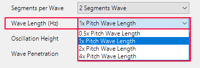
    Wave Length will determine oscillation frequency, or how often it will attempt to break the chips per spindle revolution.
    Select from the dropdown between 0.5x pitch, 1.0x pitch, 2.0x pitch and 4.0x pitch

    Wave length set to 1.0x Pitch, will move the tool in and out of the material for every revolution.
    Wave length set to 2.0x Pitch, will move the tool in and out of the material for every second revolution.
    The tool will be in sync with the thread in the Z axis during all wave motions while the X axis moves in and out of the material.

    Keep in mind that spindle RPM can affect the ability to accurately run at different wave lengths.
    A small diameter and high spindle RPM can cause the machine's X axis to not fully reach the peaks of each wave before it continues to the next wave.

    Other factors can also impact this from machine to machine, such as parameters for acceleration/deacceleration or mechanical backlash in the ballscrew.
    This can be compensated with a combination of either longer wave length, lower spindle RPM and higher oscillation height.


    Oscillation Height (Back to top) (Back to Wave Parameters)

    Oscillation Height is the effective wave height.
    Select from the dropdown between 1.25x Stepdown Xr, 1.50x Stepdown Xr, 2.00x Stepdown Xr, 3.00x Stepdown Xr and 4.00x Stepdown Xr.

    Stepdown Xr is the cut depth that is set in Machining tab (Tab 4). Setting the oscillation height to 2.00x Stepdown Xr, the tool will move out of the material with a height twice of the current cut depth (Stepdown Xr).


    Wave Penetration (Back to top) (Back to Wave Parameters)

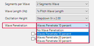
    Wave Penetration will make the tool to oscillate a set amount past the following straight threading passes.
    Depending of the material being machined and if chips not breaking properly with the tool, it can help with setting a penetration percentage to better break the chip for the following straigt pass.

    Select from the dropdown the amount of penetration. Selecting No Penetration will do the wave movements at the same diameter as the straight threading passes.


    Apply Chipbreaker on every second cut (Back to top) (Back to Wave Parameters)

    Enable this to apply chipbreaker waves on every second cut. This will shorten the machining time.

    Enable Chipbreaker on Finishing (Back to top) (Back to Wave Parameters)

    Enable this to apply waves on the finishing passes. By default waves will only be applied on the roughing passes.


    Options for visual geometry (Back to top)

    Draw Tool Coordinates as Points (Back to top)

    Enable to to create coordinate points for all calculated thread passes.
    All coordinate points represent the actual machining tool coordinates used when machining.

    Draw Tool Coordinates
    Draw Coordinates as Points

    Draw Tool Wireframe for all cuts (Back to top)

    Enable to draw the current tool geometry from the Tooling tab (Tab 3) as geometry inside the thread profile for all threading passes. This can be useful during setup of the thread.

    Draw Tool Coordinates
    Draw Tool Wireframes

    Keep Tool Wireframe on screen (Back to top)

    Enable to keep the tool wireframes on screen for each pass.

    Draw Tool Coordinates
    Keep Tool Wireframe

    Draw Texual Thread Data (Back to top)

    This will write thread information such as Major/Minor diameter, TPI and Pitch, etc as geometry. (Currently not available)

    Draw Profile over whole thread (Back to top)

    Enable to loop the thread profile geometry along the entire length of the thread. From Thread Start Z to Thread End Z in Machining tab (Tab 4)
    Due to a limitation set in GibbsCAM, max 100 loops will be drawn.

    Draw Tool Coordinates
    Draw Profile over whole thread -OFF Draw Profile over whole thread -ON

    Draw Stock as Red geometry (Back to top)

    Enable to draw a red outline for the roughing stock. The red line will be parallel to the thread profile with distance as the Roughing Stock set in Machining Tab (Tab 4).
    Red stock geometry is just a visual reference, and will not have any significance to the roughing process.

    Draw Tool Coordinates
    Draw Stock as Red geometry -ON Draw Stock as Red geometry -OFF

    Draw Tool Gouges as Red Wireframe (Back to top)

    Enable to draw a red tool wireframe if the tool geometry gouges or crosses the current thread profile.
    Tool Monitor needs to be enabled for this to be effective.

    Example shows a standard 35° VBMT insert and how it gouges along an Acme thread profile. Any detected gouges will be excluded from any toolpath generation.

    Draw Tool Coordinates
    Tool Gouges as Red Wireframe

    Draw Toolpath Lines (Back to top)

    Enable to draw the toolpaths for all threading passes as line geometry, this can be useful to visualize the toolpath without processing GibbsCAM threading operations.

    Draw Tool Coordinates
    Draw Toolpath Lines


    Control buttons at the bottom (Back to top)

    rough_cut fin_cut material do_rough do_fin process online_guide save_data do_it
    Use the buttons at the bottom of the ThreadTracer dialog to turn on or off actions to make.

    Rough Cuts (Calculated) (Back to top)


    Holds information of the calculated Rough Cuts in the current programmed thread. 'amount of cuts' [ hh:mm:ss ]
    Rough Cuts 60 [ 00h 04m 01s ] means roughing the current programmed thread requires 60 threading passes with an estimated machining time of 4 minutes and 1 seconds.

    Fin Cuts (Calculated) (Back to top)


    Holds information of the calculated Finishing Cuts in the current programmed thread. 'amount of cuts' [ hh:mm:ss ]
    Fin Cuts 112 [ 00h 07m 29s ] means finish machining the current thread requires 112 threading passes with an estimated machining time of 7 minutes and 29 seconds.

    Est. Run Time (Calculated) (Back to top)


    Est. Run Time shows the calculated Run Time for machining, for all Roughing and Finishing passes combined.

    To improve the time estimate, you can set your machine tool Rapid Feedrate in the Settings tab. Your machines rapid feedrate can be found in the parameters of the machine.
    As there are as many rapid moves as feed moves in machining a thread, setting the correct rapid feedrate will allow for a more precise time estimate.

    If you work in metric, set the Rapid Feed in millimeters/minute. If you work in inch, set the Rapid Feed in inches/minute.
    Default values in ThreadTracer are 12000 millimeters/minute for GibbsCAM in metric and 500 inches/minute for GibbsCAM set to inches.


    Material Control ( Checkmark On/Off ) (Back to top)

  • Material Control : This will enable material control, and keep all threading cuts within the set limits. By default the limits are always set to Major and Minor diameter.
  • You can change upper and lower machining limits for Material Control in the Machining Tab.

    Do Roughing ( Checkmark On/Off ) (Back to top)

  • Do Roughing : This will enable roughing of the thread. When enabled it will run the roughing of the selected thread with the set tool parameters when pressing the 'Do It' button.
  • Do Finishing ( Checkmark On/Off ) (Back to top)

  • Do Finishing : This will enable finishing of the thread. When enabled it will run the finishing of the selected thread with the set parameters when pressing the 'Do It' button.
  • Process Ops ( Checkmark On/Off ) (Back to top)

  • Process Ops : This will enable the creation of GibbsCAM threading operations for all the calculated thread coordinates when pressing the 'Do It' button.

  • Do It Button (Back to top)

    Everything in ThreadTracer is controlled by the 'Do It' button.
    You can turn on/off options, generate visual geometry, change cut depths, change tool sizes and everything will be recalculated and updated when you press 'Do It'.
    As long as the 'Process Ops' or 'NC Postprocessor' are disabled, no GibbsCAM operations or g-code will be generated.

    Set up the all the roughing and finishing of the thread and only enable 'Process Ops' when everything seems correct. With 'Process Ops' enabled it will generate GibbsCAM threading operations.
    'Do Roughing' and 'Do Finishing' can be set individually. If only 'Do Finishing' is enabled and 'Process Ops', it will only create GibbsCAM threading operations for the finishing passes.

    Click 'Do It' button to start running the options that's selected.

    As ThreadTracer is an external plugin, there is no 'ReDo' button. If you need to change anything you must delete the threading operations in GibbsCAM and create new ones in ThreadTracer.

    If you delete the threading tool instead, all the operations in GibbsCAM that used that tool will be removed, this is often faster than selecting multiple operations with scrolling for deletion.
    ThreadTracer will always create a new tool based on tools settings from the Tooling tab (Tab 3) if no previous tool exists.

    If you are using NC Tracer to generate g-code for machining, Process Ops should be disabled(off) and instead enable 'NC PostProcessor' in Tab 7.


    Save Data Button (Back to top)

    Click 'Save Data' to store the current thread setup into the GibbsCAM program

    It will create a new data entry if its a new thread, after the thread setup is stored the button will change to 'Update Data'.
    This way you can store and update the same thread entry, and not create a completely new thread entry every time the 'Save Data' is clicked.
    If you need to create a new data entry in the GibbsCAM part, you must close ThreadTracer and restart it, and it will now start with a new data entry.

    With version 4.32 and higher its not necessary to use 'Save' button. All thread data from ThreadTracer are written to each operation and retrievable by using 'Get From Op' button instead.


    These lines of text can also be copied and pasted into other GibbsCAM programs, to quickly recreate the thread without typing in all the parameters again.

    Delay Timer (Back to top)


    Visual Delay Timer for in between each calculated thread pass.
    The Delay Timer can be useful for delaying the visual geometry drawn in GibbsCAM. If something seems off, it can sometimes help track the error with a delay and confirm that every pass is done correctly.
    Delay Timer was initially used in development of ThreadTracer, but kept it as it can be useful to slow things down if there is a suspicion of some passes not being laid out correctly.


    Online Guide Button (Back to top)

    Online Guide button will open this ThreadTracer documentation in a new web browser window.
    ThreadTracer will parse information on what thread style and tab thats currently open, and redirects the web browser to the relevant page.
    Clicking the 'Online Guide' while in Stub Acme and Tab 5, will open the documentation for Stub Acme and Tab 5.

    Advanced Entry & Retract (Link) (Back to top)

    This feature is available in all versions of ThreadTracer v4.35 and up.
    Advanced Entry & Retract allows you to select the placement of the thread on the part using point geometry instead of setting start and end using numbers.

    This can be used for threads that require special placement behind a feature or around an obstacle.

    Advanced Entry
    • Part for threading
    Surface for threading
    Obstacle

    Setup the thread profile and place the thread machining positions outside the part using 'Thread Start Z' and 'Thread End Z'

    Advanced Entry

    Place geometry points to be used as an extended toolpath for the threading cycle. These points can quickly be placed freehand with mouse with using 'Mouse Point' in the Geometry Palette.
    The tool will always start where you placed the thread profile, so place points to guide the tool to the surface on the part.
    For this example, the surface that will be threaded are behind this obstacle so we need to place points to guide the tool around.

    Advanced Entry

    To designate a point to be an entry or retract point, select the point, right-click a point and select "Change feature from "WALL" to "AIR".
    Do this to every point where the tool needs to move in air.

    Advanced Entry
    Entry point 1
    Entry point 2
    Retract point 1
    Retract point 2
    Thread point 1
    Thread point 2
    Thread point 3
    Thread point 4

    By selecting these points in a spesific order, you select the points used for entry, points used for thread surface and points used for retract and return back to start.
    All points that have been set to "AIR" (red) will automatically be set and used as entry and/or retract points by ThreadTracer.

    Points that are normal (yellow) will be used as thread surface.
    Thread point 1 -> 2 will be equivalent to a Run-In angle, therefore you can place Thread point 1 in an angle in relation to Thread point 2.
    Thread point 2 -> 3 will be equivalent to 'Thread Start Z' and 'Thread End Z'.
    Thread point 3 -> 4 will be equivalent to a Run-Out angle.
    Points to be used as thread surface needs to be sets of 4 points.

    All red points selected after normal points (yellow) will automatically be used as retract points by ThreadTracer.

    Select points by holding CTRL key while you click and select the points in the order you want the tool to move.

    Advanced Entry
    1.
    2.
    3.
    4.
    5.
    6.
    7.
    8.

    With the points selected, pressing 'Do It' in ThreadTracer will bring up a window with information about the points.
    The points are automatically sorted and arranged as a new toolpath in the same order as you selected the points.

    Confirm to use the points as a guided toolpath by clicking 'Yes' in the window.

    Advanced Entry

    The new toolpath will be built with colored lines to visually identify the different features.

    Yellow lines represent entry toolpath.
    Green lines represent the toolpath for the actual thread.
    Red lines represent retract moves for the tool (rapid moves).

    Yellow lines will be output as part of the thread, ie tool moves with G32/G33 to keep the tool and spindle in sync.

    Advanced Entry

    The new point based toolpath will stay in memory until you close ThreadTracer or select new points again.
    Generate roughing and finishing operations or adjust parameters for cutting and recreate operations, and it will use the point based toolpath.

    Advanced Entry

    Multiple Thread Surfaces / Synchronized Lefthand & Righthand threads (Back to top)

    To do multiple surfaces for threading, place points in sets of 4 on the part.

    Advanced Entry

    Point 3 and 4 and point 7 and 8 are placed on the minor diameter of the thread.
    Point 2 and 5 and point 6 and 9 are on major diameter.

    Advanced Entry
    1.
    2.
    3.
    4.
    5.
    6.
    7.
    8.
    9.
    10.
    11.

    In this example, we want to machine a synchronized righthand and lefthand rope thread on the part.
    After selecting the point that will run out of the first rightland thread(pt.5), select the entry point for the lefthand thread (pt.6) and select the rest of the points in Z+ direction. (pt 7,8,9)

    If its required for the outer start thread helixes to be oriented equally on the part, start by setting the points 3. and 7. to have a distance relative to the pitch of the thread (whole revolutions).

    If the pitch is 0.5", start with setting the distance between points 3. and 7. to whole revolutions. For example 30 x 0.5 = 15", meaning distance between point 3. and 7. to be 15"

    If the placement of point 3. and 7. needs to be adjusted, translate the points the same amount in each direction.

    Same with the length of the thread surfaces, distance between point 3. and 4. and point 7. and 8. must be identical length.
    Advanced Entry
    1.
    2.
    3.
    4.
    5.
    6.
    7.
    8.
    9.
    10.
    11.

    Confirm to use the points as a guided toolpath by clicking 'Yes' in the window.

    Advanced Entry


    Advanced Entry


    Advanced Entry


    Page accessed : 452 times