Machining Tab
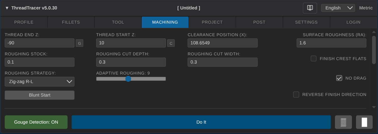
Thread End Z
Set absolute position where the thread will stop.
Thread Start Z
Set absolute position where the thread will start
Start Z needs to be minimum one pitch distance outside material, as the tool will rapid down to each cut coordinate before entering threading mode
If the thread need to start directly into material, you can set a Run-In to make a smooth entry into the material.
Clearance Position (X)
Set absolute X position where the tool will rapid to every time it re positions in between passes
Roughing Stock
Set the amount of material to leave for finishing.
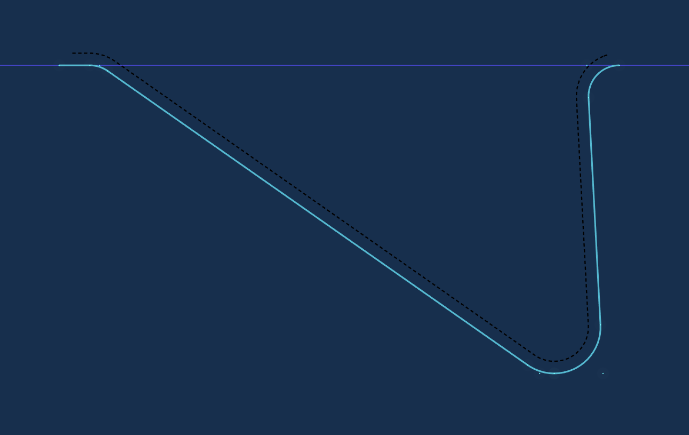
The roughing stock are indicated by a black dotted line and offset the amount of stock distance from the main thread profile.
Roughing Cut Depth
Set the depth of cut for roughing.
Roughing Cut Width
Set the width of cut for roughing.
Roughing Strategy
- Left to Right
- Right to Left
- Zig-zag R-L
- Zig-zag L-R
- Center Out
- Sides Only
Left to Right -- Cycles the roughing passes from right side to left side in the Z direction.
Right to Left -- Cycles the roughing passes from left side to right side in the Z direction.
Zig-zag R-L -- Cycles the roughing passes in an alternating pattern, first passes in right-left Z direction, then left-right on the next passes.
Zig-zag L-R -- Cycles the roughing passes in an alternating pattern, first passes in left-right Z direction, then right-left on the next passes.
Center Out -- Places the first roughing pass in the center of the thread, and cycles the rest of the roughing passes towards the sides.
Sides Only -- This will only do roughing passes along the sides of the thread profile.
Adaptive Roughing
- None
- Conservative
- Detailed
- Aggressive
- Aggressive 2
- Aggressive 3
- Aggressive 4
The Adaptive Roughing options in ThreadTracer will dynamically adapt each cut along the curved surface at the root of the profile.
The cut depth will continuously vary to maintain a uniform and parallel surface to the thread profile.
With Adaptive Roughing enabled, the roughing tool will start cutting using the set Roughing Cut Depth and decrease to smaller depth of cut at the root of the thread.
To get the same effect without using Adaptive roughing, the only option are to set the depth of cut smaller than needed, significantly increasing the overall amount of cuts and time to machine the thread.
Finishing Options
Surface Roughness (Ra)
Set the surface roughness for finishing passes in Ra.
Ra is calculated as the Roughness Average of a given surface. Lower Ra number produces higher number of finishing passes, higher Ra number produces less finishing passes.
If the surface requirement is given in RMS, you need to convert it to Ra.
The table below shows comparisons of various surface roughness scales.

Finish Crest Flats
Only applies for finishing passes. This checkmark is disabled by default.
When enabled, this will add finishing cuts over the crest surface of the thread profile.
This can be useful for threads with tight tolerances as all surfaces will be relative to the same tool offset.
No Drag
Only applies for finishing passes. This checkmark is enabled by default.
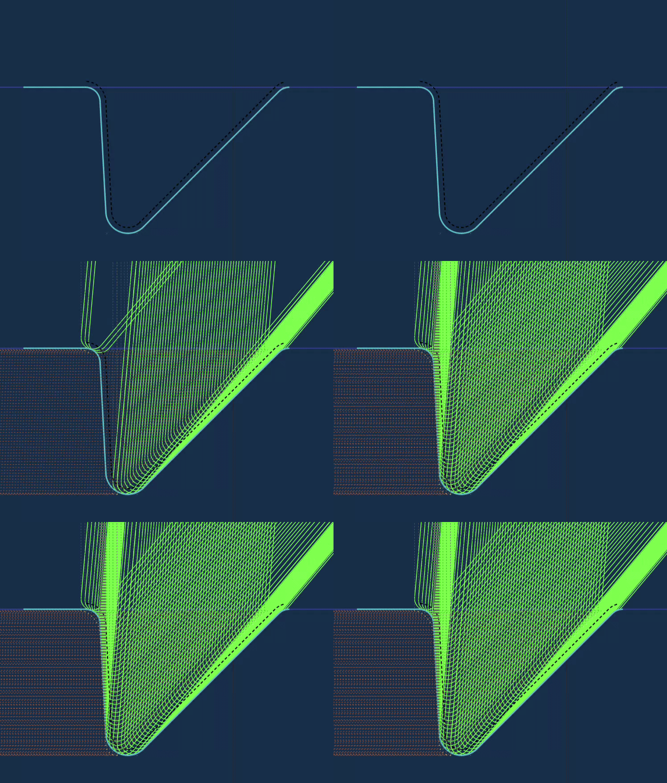
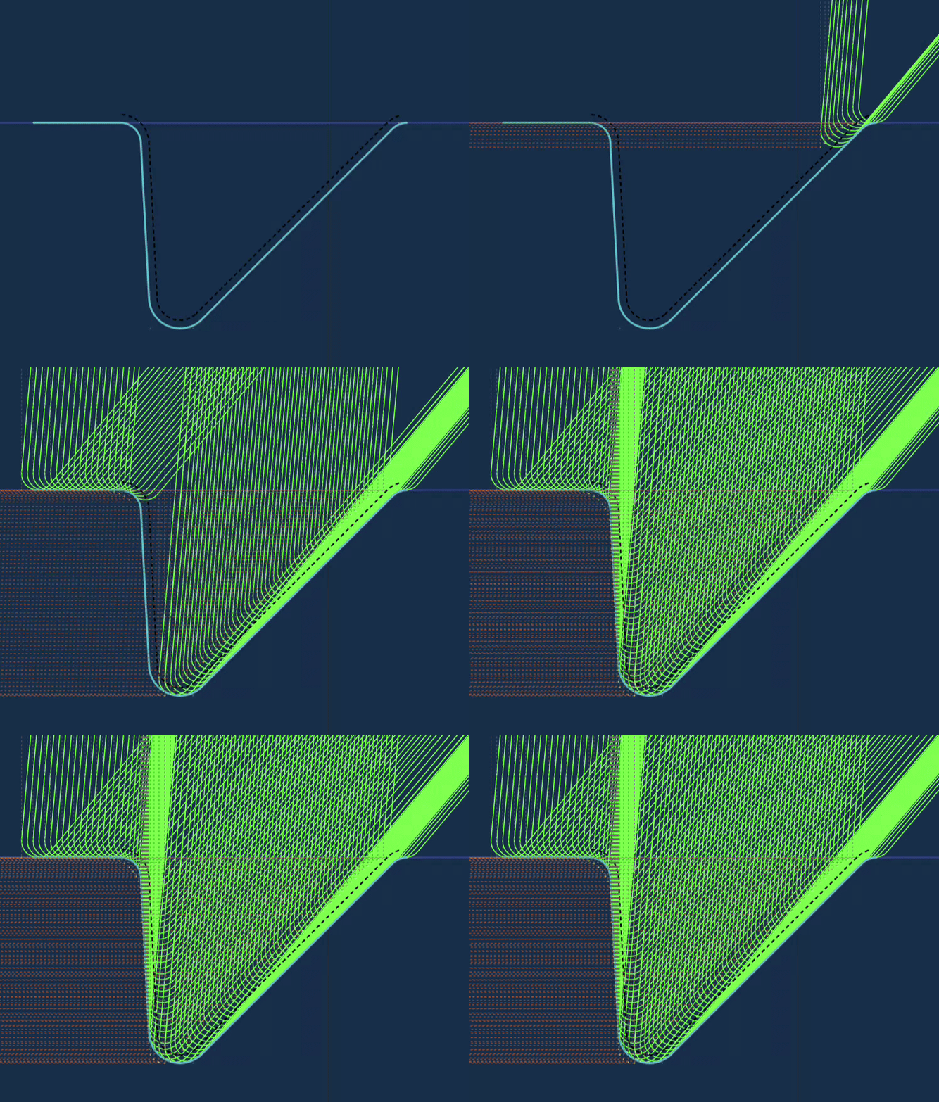
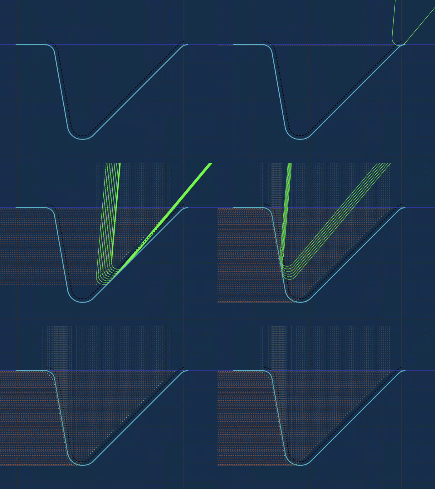
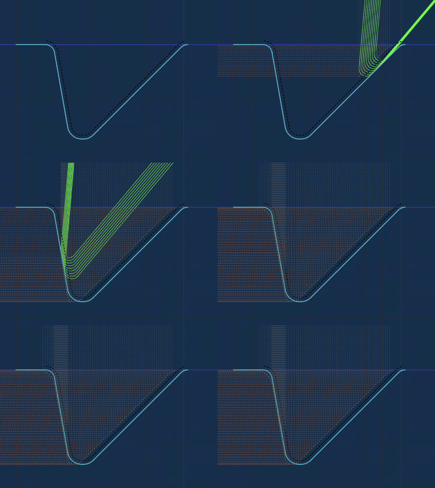
When this checkbox is enabled, the thread profile is automatically split into two segments that will make sure the insert always cuts "downhill".
The finishing passes always starts at the crest of the thread and follows the shape down to the root of the thread.
Then it repeats and do the other segment.
With this checkmark off, the tool will follow the thread profile for the finishing passes from one side to the other and machine "uphill".
Reverse Finish Direction
Only applies for finishing passes. This checkmark is disabled by default.
This will flip the finishing passes start direction, if it started on the right side, reverse will make it start on the left side.
Blunt Start
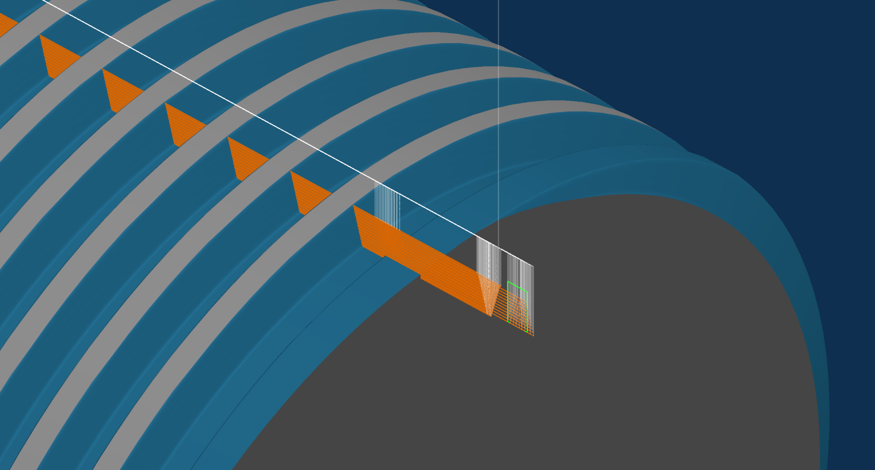
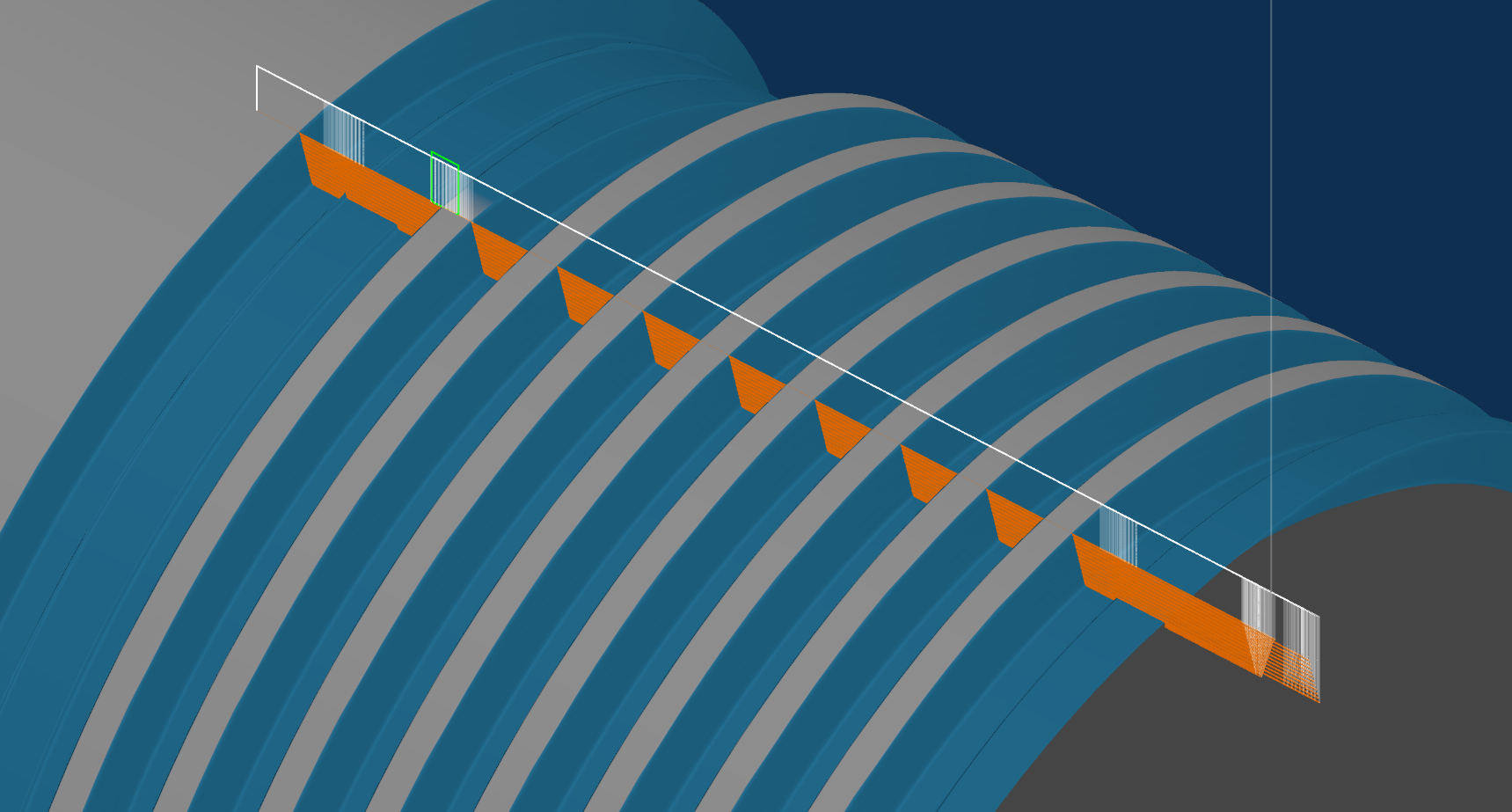
Automatically apply Blunt Start / Quick Start threads. For removal of incomplete threads on the part.
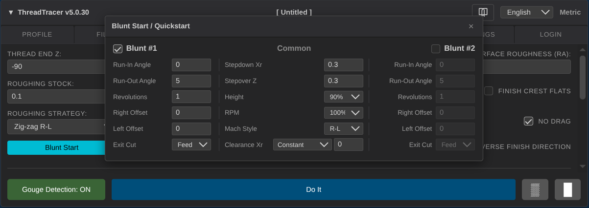
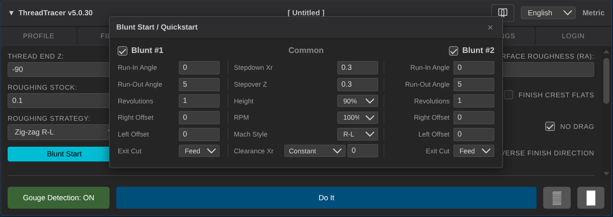
Bluntstart / Quickstart parameters
Blunt #1
This will enable Blunt Start threads to be calculated when pressing the Do It button. All machining will be done with the same tool as the main thread.
( as defined in Tooling tab )
It can be a good practice to set up the main thread first, and then turn off Roughing and Finishing and set up blunting parameters without having to calculate everything every time you tweak something.
Stepdown Xr ( Blunt )
Stepdown Xr : Set the depth of cut for all blunting passes.
Stepover Z ( Blunt )
Stepover Z : Set the width of cut for blunting passes.
Revolutions (Blunt)
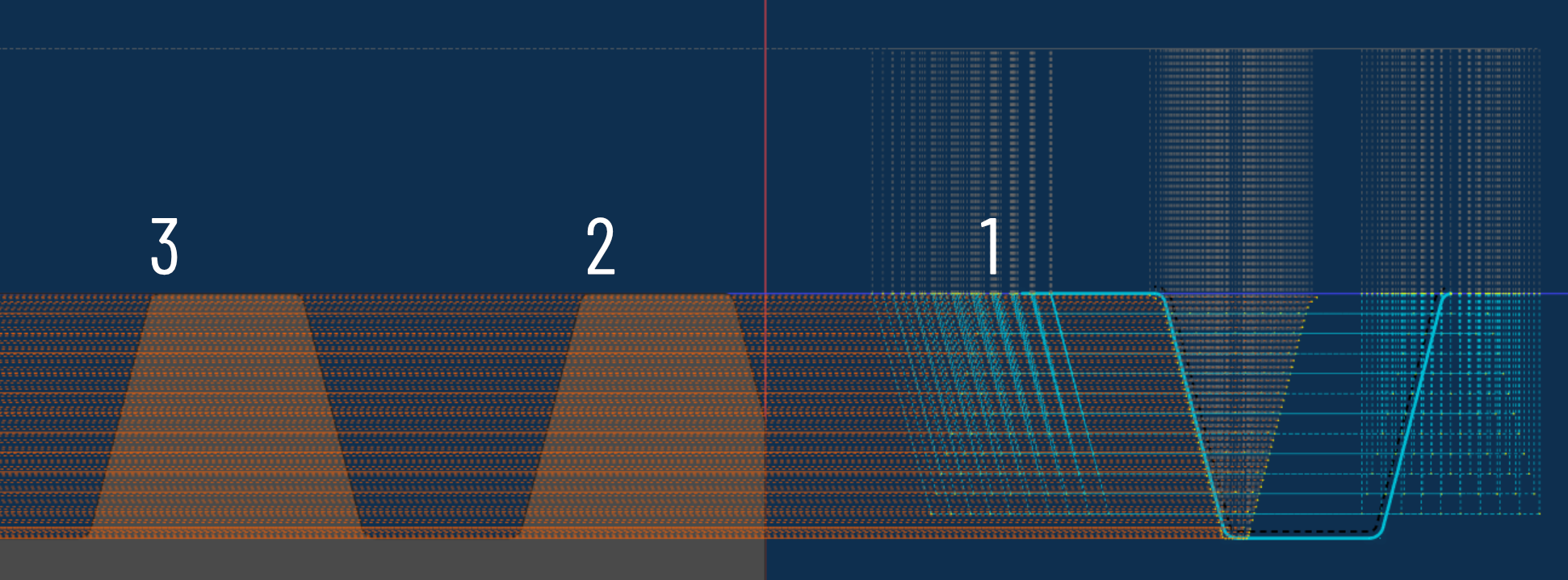
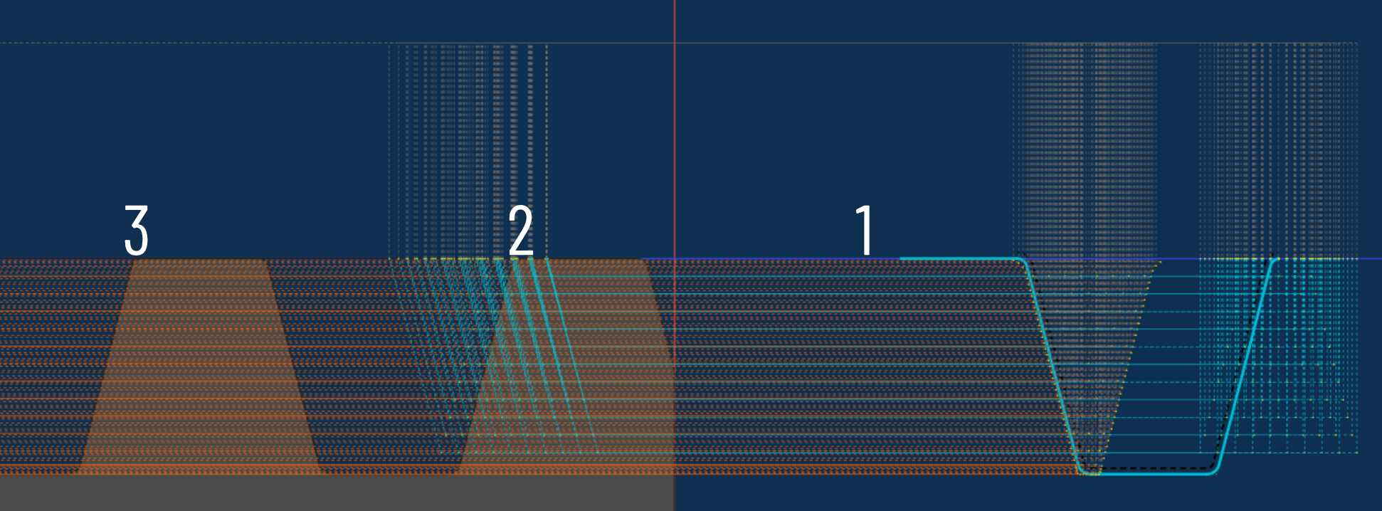
Set the amount of revolutions of thread to remove. This is calculated from Thread Start Z in Machining tab (Tab 4) Depending of how far the Thread Start Z are set from the material, set any number here until it reaches over the incomplete thread. Use number with decimal to adjust in between revolutions e.g. 1.5 or 2.2
Spindle RPM ( Blunt )
Spindle RPM : Set to use 100% or 50% RPM for when machining blunting passes.
100% will use the same RPM as the roughing passes, 50% will use half the RPM as the roughing passes.
If the machine can handle changing RPM and be synchronized, a lower RPM can help the machine to perform these short and fast moving threading toolpaths.
DIfferent machine vendors have this as a seperate option to change RPM during threading and keep the thread synchronized. If your machine are not equipped with this, use Spindle RPM at 100%
Run-Out Angle ( Blunt )
Set an run-out angle for the tool to exit the material. 0 is straight up and will produce the shortest blunt.
Larger angle will make the tool to use longer time to move out of the material so the distance of the blunted thread will be longer.
Run-Out Angle are not necessary for when exiting into a thread relief or air, as when making a blunted thread at the end of the thread.
Run-In Angle ( Blunt )
Set an run-in angle for the tool when entering material. 0 is straight down and should only be used if starting in air.
Larger angle will make the tool to use longer time to reach the cut depth so the distance of the blunted thread will be longer.
Run-In Angle are not necessary for entry into air, as when making a blunted thread at the start of the thread.
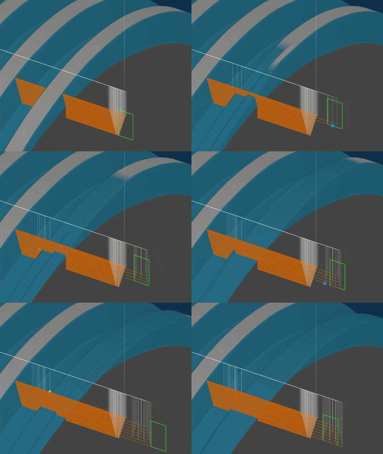
Height to remove ( Blunt )
Height to remove : Set the percentage of thread height to remove. 100% will remove the thread down to the root. 90% will leave a tiny amount and often results in a better finish.
Select from the dropdown menu what percentage of thread height to remove. 50%, 60%, 70%, 80%, 90%, 95% and 100% are available.
Mach Style
Select machining style for blunting.
- R-L (Right-Left) : Cycles the blunting cuts from right side to left side in the Z direction.
- L-R (Left-Right) : Cycles the blunting cuts from left side to right side in the Z direction.
- ZZ R-L (ZigZag R-L) : Cycles the blunting cuts in an alternating pattern, first pass in right-left Z direction, then left-right on the next pass.
- ZZ L-R (ZigZag L-R) : Cycles the blunting cuts in an alternating pattern, first pass in left-right Z direction, then right-left on the next pass.
- C-Out (Center Out) : Places the first blunting pass in the center of the thread, and cycles the blunting cuts towards the sides.
- Sides (Sides Only) : This will only do blunting passes along the outside of the thread profile.
Offsets ( Blunt )
Right Offset and Left Offset can be used to offset the blunt position in the Z axis. Use positive and negative numbers for both directions.
Right Offset
This will offset the blunting positions on the right side of the thread profile.
Left Offset
This will offset the blunting positions on the left side of the thread profile.
The default Right and Left offsets of 0 are the calculated minimum width and position the current tool need to remove the thread down to the root. Various machine tool states with different parameters, ballscrew backlash, acceleration settings, etc can make different machines leave different results when blunting threads.
When running these blunt passes for the first time, always try to run with conservative depth of cuts and observe the machining process. If the tool leaves a sliver of thread after the process, you can adjust and center the blunt toolpath with Right and Left offsets.
Widen the cutting area with adjusting Right and Left offsets in opposite directions (± Z axis). Move the cutting area with adjusting Right and Left offsets in the same directions (± Z axis).
Blunt End
Blunt #2

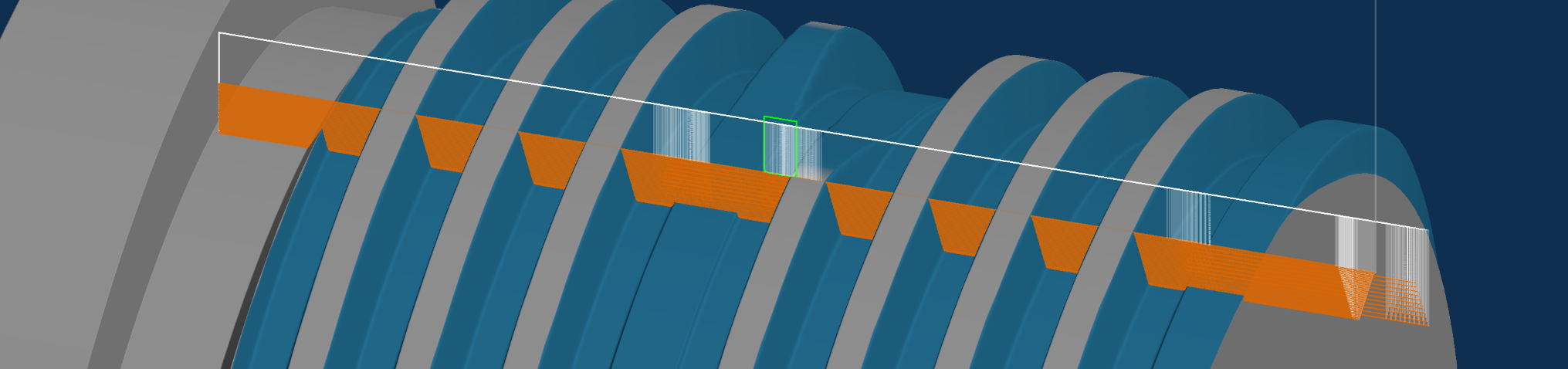
By moving the blunt offsets towards the end of the thread, you can machine away the sharp portion at the end of the thread.
Move the blunt offsets by counting the number of threads / revolutions and multiply this with the pitch of the thread. Lets say for 15 threads / revolutions on a 4 TPI thread, set both Right Offset and Left Offset to -15 6.35 (-95.25mm) or if you work in inches, -15 0.25 (-3.75in)

You can enter mathematical operations directly in all the input boxes, e.g. type -15 * 6.35 and hit Tab key on keyboard and it calculates.
Move positions anywhere on the thread, offset the position with multiplying revolutions with the pitch of the thread, and amount of revolutions to remove.
Exit Cut ( Blunt )
Exit Cut : Set feed exit or rapid exit for when exiting out of the thread. Setting this to rapid will use G0 for exiting out of the thread.
Feed Exit will move the tool out of material with the same feed as when threading and follow the set Run-Out angle. Run-Out angle will determine the length of the blunted thread. Rapid exit will move the tool out of material with rapid feedrate and will produce a short and steep blunted thread.
Run-In and Run-Out
Scroll down in the Machining tab to access these options

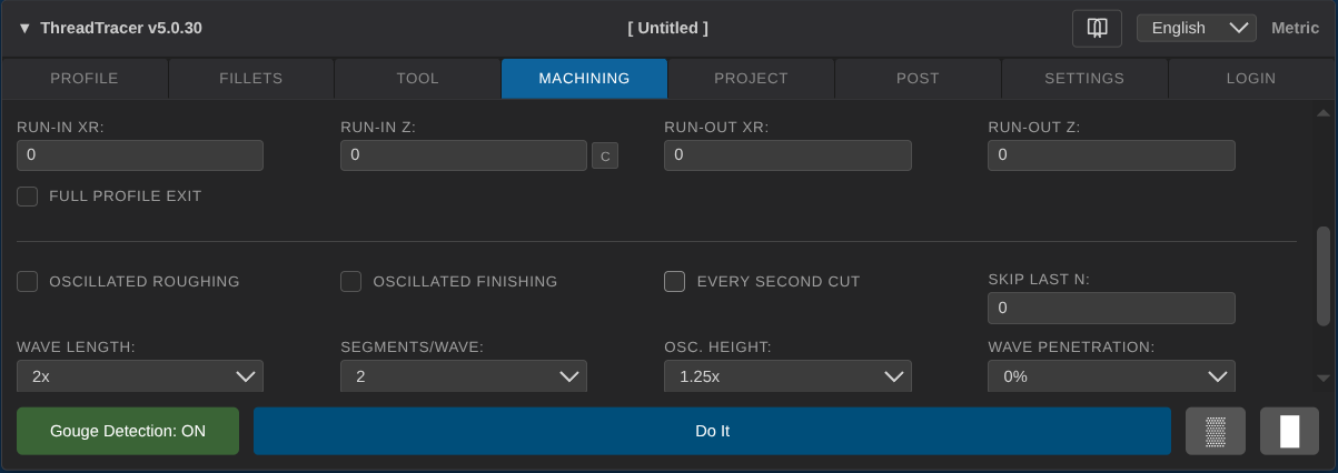
Run In values can be used if the tool needs to begin a certain distance away from the actual thread start in order to create a syncronized entry.
The Run-In Z distance allows you to designate a distance along the Z axis to start the threading passes.
The Run-In Xr distance can be used in conjunction with the RunIn Z distance to start the thread at an angle.
The Run-Out values allow you to designate a distance and angle for the tool to make a syncronized exit out of the thread and function the same as the Run-In values.
The actual Thread Start Z and Thread End Z values specify where along the Z axis the thread will begin and end so any Run-In or Run-Out values will be added on the actual length of the thread.
Run-In Xr
Set the amount for run in [X axis]
Set this to atleast the same value as Thread Height (or slightly higher) in order to fully enter the thread while syncronized
Run-In Z
Set the amount for run in [Z axis]
Set this to the same value as RunIn Xr to make a 45 degree angle syncronized entry.
If it is spesified that the lead in must be one rotation (1 pitch) or half a rotation (0.5 pitch) you can calculate this from the thread pitch.
inch units
For a 4TPI thread, the pitch is 0.25 (1/4), so use 0.25 as Run-In Z for a full rotation, or 0.125 for a half rotation lead in.
metric units
For a 4TPI thread, the pitch is 6.35mm, so use 6.35 as Run-In Z for a full rotation, or 3.175 for a half rotation lead in.
Run-Out Xr
Set the amount for run out [X axis]
Run-Out Z
Set the amount for run out [Z axis]
Examples Run-In and Run-Out
When the thread starts outside the material (starts in air) there is no need to use Run-In.
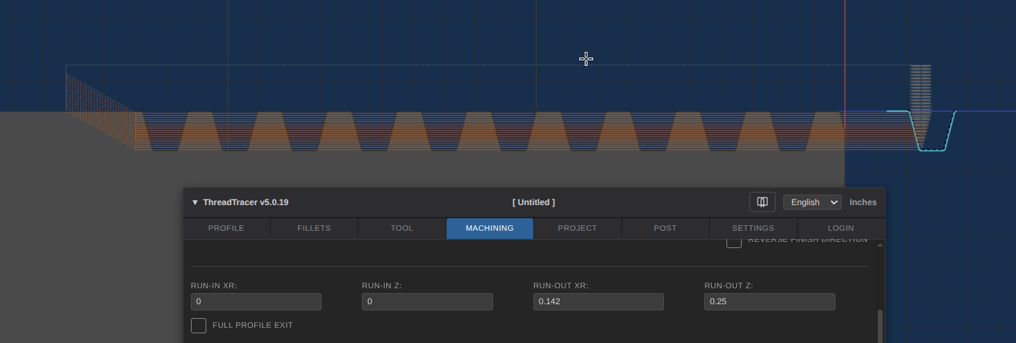
When the thread needs to be placed directly on the part, use Run-In to add a smooth syncronized lead-in into the material.
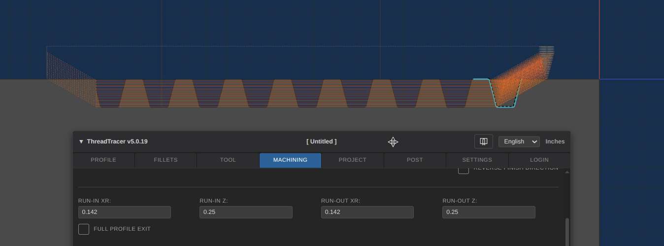
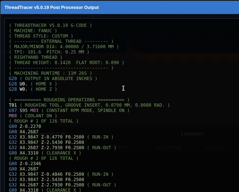
Full Profile Exit
With Full Profile Exit enabled, it will extend the end position past Thread End Z to follow the thread profile out of material.
With using Full Profile Exit, the exit of the thread will look similar to as if the thread was machined with a tool with the same profile as the thread.
This can also be used if the thread have no relief groove, and will produce a smoother end transition to the thread.
Adaptive Finishing
Adaptive Finishing
Toggle the checkmark to enable Adaptive Finishing

Adaptive Finishing dynamically adapts a denser stepover for finer surface finish around fillets.
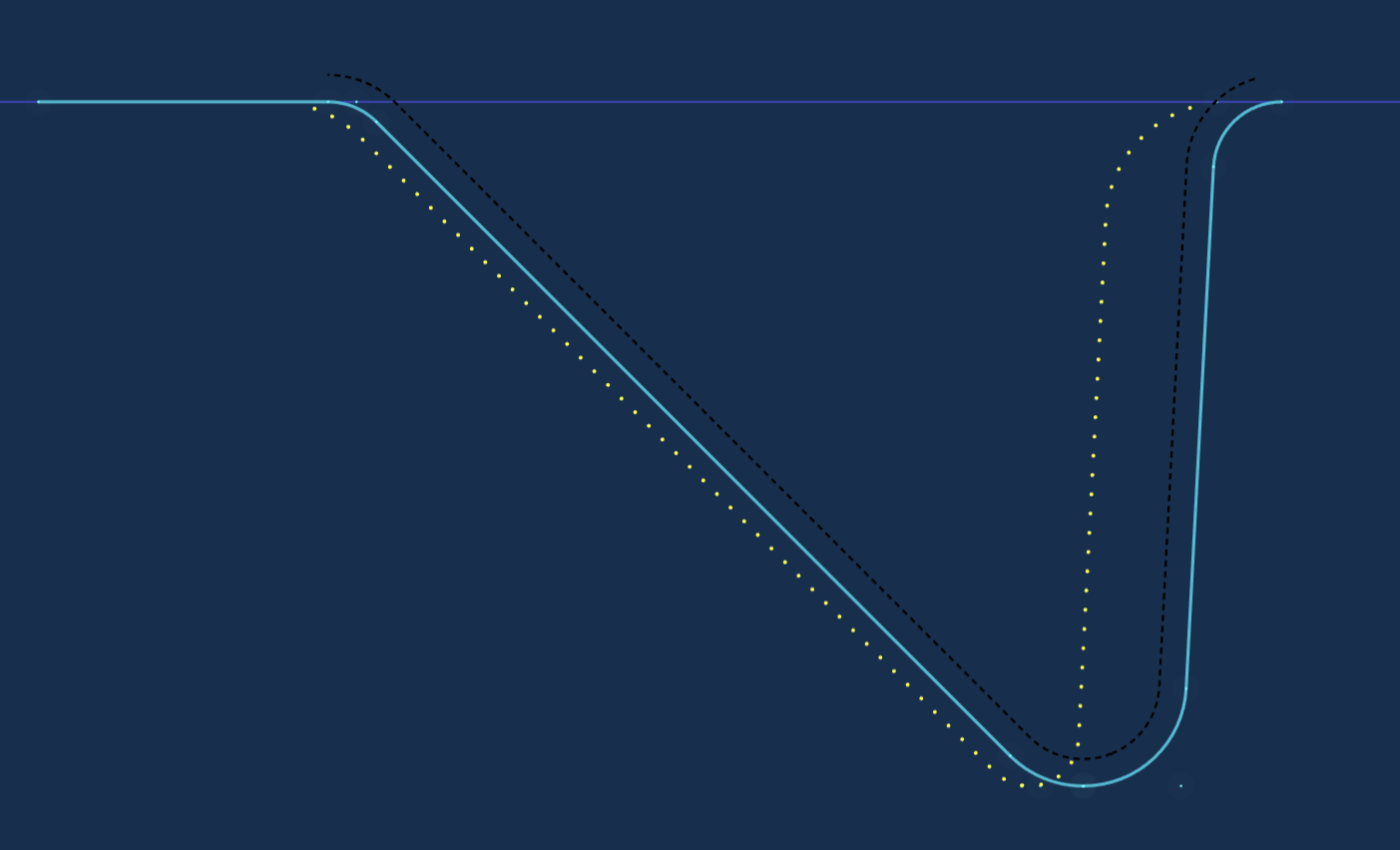
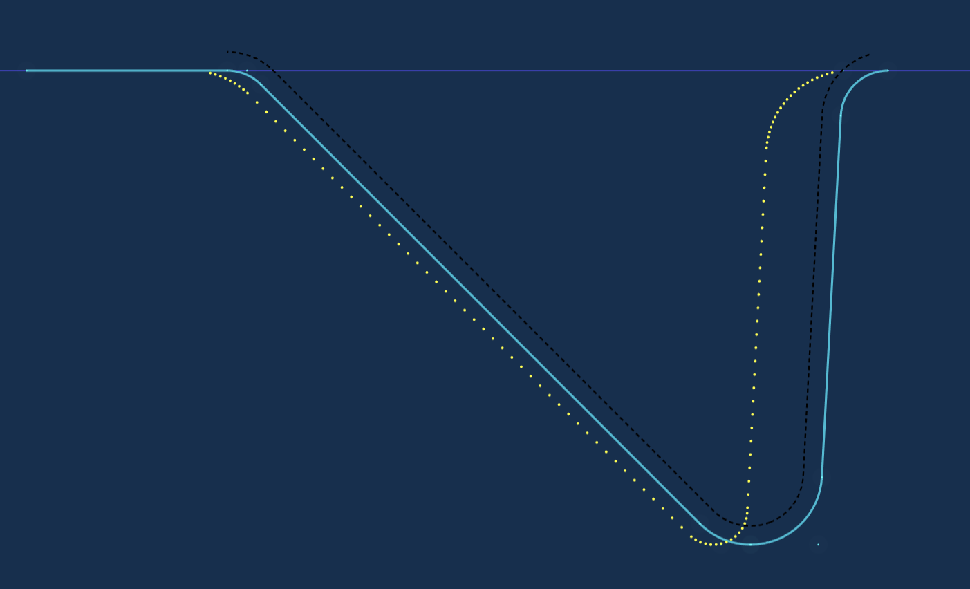
Angle Threshold
Set the angle threshold for Adaptive Finishing
Curve Density
Drag the slider to set density for Adaptive Finishing
Look-Ahead
Drag the slider to set the look ahead distance for Adaptive Finishing